By the first picture of schematic (RIAA-phono stage) I miss the device for the input capacity. Which value was inside as standard ?ask ZM
in case that you have one in front of you - you can send me missing values in phono feedback loop

Thanks for advice.
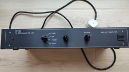
Thank you, very much.speaking of post #2 , first (left) pic is line stage , while second (right) is RIAA
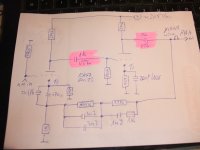
150p is drawn and noted as input capacity governor
plus Herr Mueller effect
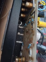
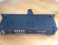
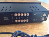
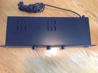
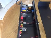
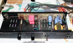
I am looking for images of the PCB, but the bottom view, so as the PCB layout.
Maybe this helps to avoid removing the complete PCB for troubleshooting, which is extremely time-consuming.
Thank you very much for upload.
Maybe this helps to avoid removing the complete PCB for troubleshooting, which is extremely time-consuming.
Thank you very much for upload.
A friend of me observe issues regard that - go to post #14 about
http://www.diyaudio.com/forums/anal...tion-broadcast-sw-stations-2.html#post3166962
Why don't you make preamps with tubes like ecl86....ecl84.... Manley can't be a professional in hifi. I had the chance to copy preamps from Japanese manufacturer many times. They are high end. And in Very expensive market. But you can build. Anyway, you can ignore it and go the old way.

in the attachment (first image) the bottom view.I am looking for images of the PCB, but the bottom view, so as the PCB layout.
Maybe this helps to avoid removing the complete PCB for troubleshooting, which is extremely time-consuming.
Thank you very much for upload.
In the second schematic of post #3 there are no values noted for the RIAA equalizing network. Who know the values ?
Any experiences concerning replace the present couple capacitors (VTL labeled) by this one from Jantzen Audio ?
http://www.jantzen-audio.com/superior-z-cap/
https://quint-store.com/media/files...dd066ec56d5db/Jantzen Superior-Z-Cap-List.pdf
Attachments
Thank you for your information. Professional hi-fi manufacturers never make studio preamps, mixers, and compressors...condenser mic .....Like them or not, Manley Labs must certainly be considered as professionals in audio.
They have been around for about 50 years, and have received very good reviews.
Manley has always done both.
https://en.wikipedia.org/wiki/Manley_Laboratories
Not that unusual, Shure also does.
https://en.wikipedia.org/wiki/Manley_Laboratories
Not that unusual, Shure also does.
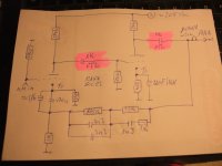
In the attachment my own created schematic of the device in question.in the attachment (first image) the bottom view.
In the second schematic of post #3 there are no values noted for the RIAA equalizing network. Who know the values ?
Any experiences concerning replace the present couple capacitors (VTL labeled) by this one from Jantzen Audio ?
http://www.jantzen-audio.com/superior-z-cap/
https://quint-store.com/media/files_public/75238661f2268347a6bdd066ec56d5db/Jantzen Superior-Z-Cap-List.pdf
Main difference which I note to VTL's genuine circuit diagram are between
1) - the values of caps in the signal pad labeled with VTL (1K/22K = 1nF/22nF vs. 0,1µF and 0,22µF in the second schematic of post 3) and
2) - the not present cartridge input load capacitor in parallel to the 47K5 resistor (150pF in the second schematic of post 3)
Attachments
Last edited:
the marked values on caps in the signal pad (1K/22K - labeled with VTL) haven't to do with those in real life. = 100 nF
Follow values I note by measuring with multi meter:
1K = 100 nF (0,1µF)
22K = 220nF (0,22µF)
P.S.: I want to know, what kind of bypass foil capacitor is a good choice to solder in parallel to the 220µF (between cathode and GND) - taking into account the limited space ?
Either one decide on an MKS/MKT version with a higher value or with the same size for a lower value - but then with the higher-quality - i.e. MKP/FKP version (due the low voltage condition on that point a 63V version is enough).
Any experiences ?

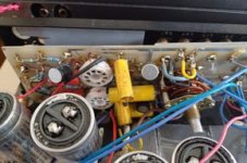
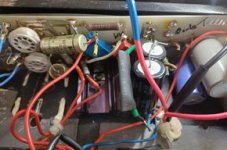
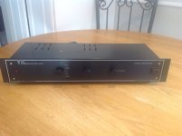
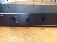
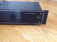
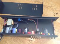
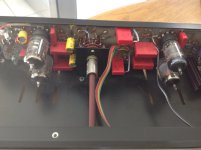
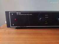
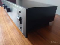
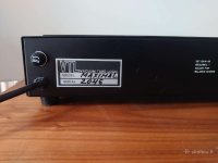
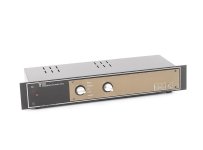
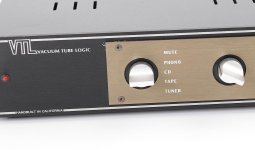
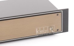
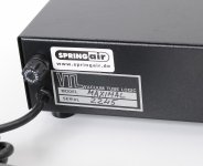
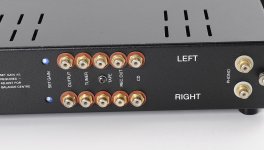
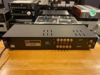
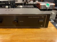
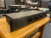
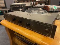
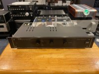
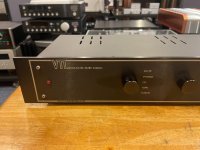
some images from various devices of this model
Attachments
-
 VTL-Maximal-2102-front.jpg320.8 KB · Views: 110
 -
 VTL-Maximal-2102-bottom.jpg412.9 KB · Views: 108
 -
 VTL-Maximal-2102-front-left.jpg362.4 KB · Views: 106
 -
 VTL-Maximal-2102-front-right.jpg327.7 KB · Views: 91
 -
 VTL-Maximal-2102-rear.jpg430.7 KB · Views: 91
 -
 VTL-Maximal-2102-rear-II.jpg375.7 KB · Views: 93
 -
 VTL-Maximal-2102-top.jpg549.2 KB · Views: 110
 -
 VTL-Maximal-2102-top-open.jpg434.9 KB · Views: 117
 -
 VTL-Maximal-2102-top-open-II.jpg513.5 KB · Views: 130
 -
 VTL-Maximal-2102-top-open-III.jpg342.2 KB · Views: 118
 -
VTL Maximal short form test Stereophile-1989-09-IDX-169.pdf132.4 KB · Views: 120
-
VTL Maximal short review Stereophile-1990-01-IDX-199.pdf152.5 KB · Views: 326
more images from various devices of this model
Attachments
-
 VTL Maximal 2046 front left.jpg42 KB · Views: 83
 -
 VTL Maximal 2046 front.jpg127.9 KB · Views: 77
 -
 VTL Maximal 2046 main switch.jpg33.5 KB · Views: 78
 -
 VTL Maximal 2046 rear.jpg45.4 KB · Views: 77
 -
 VTL Maximal 2245 champ.front-I.jpg61.9 KB · Views: 70
 -
 VTL Maximal 2245 champ.front-II.jpg111.4 KB · Views: 83
 -
 VTL Maximal 2245 champ.front-III.jpg94.9 KB · Views: 72
 -
 VTL Maximal 2245 champ.front-rear-I.jpg188 KB · Views: 74
 -
 VTL Maximal 2245 champ.front-rear-II.jpg169.1 KB · Views: 67
 -
 VTL Maximal MX3009 rear.jpg109.5 KB · Views: 70
 -
 VTL Maximal MX3009 front-VI.jpg91.7 KB · Views: 84
 -
 VTL Maximal MX3009 front-IV.jpg99.5 KB · Views: 91
 -
 VTL Maximal MX3009 front-III.jpg101.3 KB · Views: 76
 -
 VTL Maximal MX3009 front-II.jpg110.6 KB · Views: 80
 -
 VTL Maximal MX3009 front-I.jpg94 KB · Views: 89
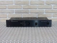
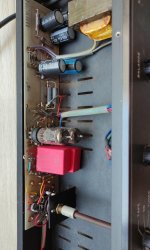
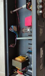
According internal images, the model "MAXLINE" is identical with the model "MAXIMAL" but without the RIAA-stage
Attachments
-
 VTL Maxline front.jpg60.8 KB · Views: 110
 -
 VTL Maxline front-II.jpg59.2 KB · Views: 102
 -
 VTL Maxline front-open.jpg332 KB · Views: 127
 -
 VTL Maxline open-I.jpg326.3 KB · Views: 119
 -
 VTL Maxline open-II.jpg66 KB · Views: 89
 -
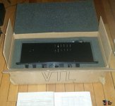 VTL Maxline package.jpg78.9 KB · Views: 90
 -
 VTL Maxline prod.check sheet.jpg83.3 KB · Views: 89
 -
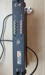 VTL Maxline rear.jpg69.5 KB · Views: 92
 -
 VTL Maxline rear-III.jpg61.7 KB · Views: 88
- Home
- Amplifiers
- Tubes / Valves
- Schematic wanted for VTL Preamp "Maximal"