Another Newby question...
Assuming you only use the balanced XLR outputs of your DAC. Is it possible to make a push pull driver stage that doesn't have/need a phase splitter stage at all? I mean, if your only source input ever is going to be the balanced XLR, why not omit the splitter stage entirely? Can anyone provide a schematic where someone has already done this?
Assuming you only use the balanced XLR outputs of your DAC. Is it possible to make a push pull driver stage that doesn't have/need a phase splitter stage at all? I mean, if your only source input ever is going to be the balanced XLR, why not omit the splitter stage entirely? Can anyone provide a schematic where someone has already done this?
Like a standard tube diff amp? It actually works much better when both grids are driven differentially, since there is no common mode signal.
The negative supply for the common cathode resistor is important for best operation.
Diagram is from https://www.atma-sphere.com/en/resources-understanding-our-circuits.html

The negative supply for the common cathode resistor is important for best operation.
Diagram is from https://www.atma-sphere.com/en/resources-understanding-our-circuits.html

Perhaps just feed the balanced input into a balanced driver stage like the driver stage of a Williamson amp.
Perhaps just feed the balanced input into a balanced driver stage like the driver stage of a Williamson amp.
I was thinking that, but it seemed too simple. Basically inject the signal into any random PP amplifiers driver gain stage after that circuits existing phase splitter, omit the circuitry upstream from there. That stage doesn't know or care "how it got split" as long as the signal is split right?
Correct. The signal to each driver triode grid is capacitor coupled, and referenced to local 0V. The voltage gain of that driver triode, and the available voltage from your DAC, will determine the voltage swing available to a PP output stage. The grid leak of the driver triode should be sufficiently high to not impose a load on your DAC output. If you use a coupling cap then it will determine the LF response. However, you won't have global negative feedback, so you will be at the mercy of a valve amp's output stage and output transformer and relatively high harmonic distortion and output impedance and noise/ripple, when compared to a ss amp, or a valve amp circuit that does include feedback.
@6A3sUMMER posted a very nice design a few months ago doing pretty much exactly what you are asking about.
I like to use input transformers to split phase myself which is effectively dpoing the same thing as using a balanced signal: no electronic phase splitter required and simple implementation.
I’ve pretty much standardized on CCS loaded dual triodes in a diff amp arrangement. Select triodes for sufficient gain to drive the output tubes. Signal to output tubes from mu output of CCS on each anode. Diode bias (LED or SiC string to appropriate grid bias value).
Simple and sounds good in my experience.
My 2 cents, ymmv etc etc
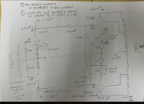
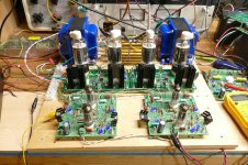
Here is an example of my earlier post. I subsequently changed to a single LED from the 2 LED string shown due to over distortion of the anode if it ever got a full 7V pk to pk input voltage with 3.4V bias and 7.5mA constant current for the 6N23P.
Voltages shown are measured values
Voltages shown are measured values
Attachments
I mean, if your only source input ever is going to be the balanced XLR, why not omit the splitter stage entirely? Can anyone provide a schematic where someone has already done this?
I think it often comes as a surprise to people that balanced amplifiers are in most ways simpler than 'regular amps'. It is the balancing (SE to PP) or unbalancing (PP to SE) process that normally takes up design effort, which you don't need here.I was thinking that, but it seemed too simple.
I hadn’t thought of the lack of global negative feedback in this kind of design before. You could still use local feedback between driver and output tube right? I have been idly thinking about a differential amp run in all pentode, both drivers and outputs. The input pentodes should have enough gain to allow decent amount of local feedback (Schade?) and still be able to drive the outputs well. Between that and the regulated screens on all the tubes the wiring will be more complicated I suppose.Correct. The signal to each driver triode grid is capacitor coupled, and referenced to local 0V. The voltage gain of that driver triode, and the available voltage from your DAC, will determine the voltage swing available to a PP output stage. The grid leak of the driver triode should be sufficiently high to not impose a load on your DAC output. If you use a coupling cap then it will determine the LF response. However, you won't have global negative feedback, so you will be at the mercy of a valve amp's output stage and output transformer and relatively high harmonic distortion and output impedance and noise/ripple, when compared to a ss amp, or a valve amp circuit that does include feedback.
My current amplifier is a differential amp with a pair of twin triode drivers and the output stage being able to run in either ultralinear or triode. It also has adjustable b+ and uses external heater supplies. It’s basically a test bed for trying out different tube combos. It has proven to not only be very flexible but also to sound very good with many combos. I wonder if the simplified feedback scheme is what allows good performance and flexibility.
You can use a 0-4-16 ohm OPT and ground the 4 ohm to get feedback. You can still have 8 ohms by adjusting primary impedance. However any common mode signal will have the full open loop gain applied to it - so you are using the OPT only to eliminate it. At least I think that correct. The issue is if the common mode signal get big enough it could cause intermodulation distortion.
A transistor concertina will perform at least as well providing several ma of current and 60v p-p outputs from 150v B+ and 12AX7 input.
Does you goal of 'good performance' include wide bandwidth?
Have you set your test bed up to try this balanced approach in its simplest form ?
Have you set your test bed up to try this balanced approach in its simplest form ?
Correct. The signal to each driver triode grid is capacitor coupled, and referenced to local 0V. The voltage gain of that driver triode, and the available voltage from your DAC, will determine the voltage swing available to a PP output stage. The grid leak of the driver triode should be sufficiently high to not impose a load on your DAC output. If you use a coupling cap then it will determine the LF response. However, you won't have global negative feedback, so you will be at the mercy of a valve amp's output stage and output transformer and relatively high harmonic distortion and output impedance and noise/ripple, when compared to a ss amp, or a valve amp circuit that does include feedback.
I'm slow, but I finally figured out why no global negative feedback. A balanced front end requires two feedback wires, but the secondary of the OPT is back to being single ended. Assuming the 4 ohm tap is truly a center tap, as someone said that can be grounded to get two feedback wires. Feedback can be done from the OPT primary side, but maybe not as effective as global FB though. To get global FB from the secondary side of an OPT with no CT would require a small phase splitter shunting the speaker right? Something purposed just to generate both feedback phases. Maybe a high input impedance transistor concertina across the OPT just to bleed off some signal to go back as NFB? That should be transparent to the speaker and regenerate both FB phases right?
You don't need a CT on the secondary for balanced feedback, but if you do use global feedback then you can no longer connect the amp to any single-ended equipment, e.g. for recording. Feedback from the primary is just about as good as global (and likely more stable). Loads of studio equipment was built that way.
https://tubecad.com/2018/11/blog0447.htm
https://tubecad.com/2018/11/blog0447.htm
Possibly a silly question, but given say for instance a Williamson amplifier or an amplifier with balanced input, is there any real disadvantage to running feedback off of each side of the transformer secondary?
Like so-

Ignoring the parts values, zeners, etc, what would be the disadvantages to running it this way? It seems like it would avoid the phase shift inherent with looping an additional stage inside, with maybe less THD reduction than the traditional way, assuming that you could keep phase shift in line? Might be better for lesser quality transformers?
Like so-
Ignoring the parts values, zeners, etc, what would be the disadvantages to running it this way? It seems like it would avoid the phase shift inherent with looping an additional stage inside, with maybe less THD reduction than the traditional way, assuming that you could keep phase shift in line? Might be better for lesser quality transformers?
- Lingwendil
- Replies: 14
- Forum: Tubes / Valves
Last edited:
Here are several variations on a common theme. The concept had been proven successful with the 80 watt screen drive amp using a pair of 6AV5 sweep tubes back in 2005 and the 300Beast in 2001. What is now the Tubelab Universal Driver Board went through a long evolutionary period to become the board seen in many of my current experiments. There were many iterations of the design with different goals in mind. The design unfolds bit by bit in the 6L6GC in AB2 thread. My involvement starts in post #70, with the UDB concept beginning in post #94. This is an old thread. It details the design of an amplifier with several people contributing to the design and the builder of the amp in Australia. Lots of good knowledge gained for all, but it is a long thread that winds on for 9 years and almost 700 posts.
I made one-off DIY PC boards of the driver design at several places along the journey ending with the UDB board in 2015. Three versions are included here. The 300Beast had a unique driver board, and there were several test versions built on the Tube Lab breadboarding system I made in
The 2009 board was a test that included some experiments. The first stage is a typical Long Tailed Pair. The extra input to the left triode included a resistor for direct connection to the speaker output for global NFB. The pot in the cathodes is used to compensate for non identical triodes in the input tube. RC coupling was used to feed the grids of the second tube to avoid cascading DC offsets.
I put CCS circuits in both the cathode and plate circuits of the second stage to test some ideas. I had been working with screen driven sweep tubes a lot at the time, so I was looking for a way to get over 300 volts peak to peak out of two tubes. Obviously without the resistors across the CCS chips the circuit will have nearly infinite gain turning itself into an SR flip-flop. Ten minutes of testing revealed that you can put CCS's in the cathode, or in the plate circuit, not both. For a good fully differential design, put the CCS in the cathode The THD will be lower. The third stage is the PowerDrive circuit needed to drive the grids of a 6L6GC positive.
The TriPent board uses a pentode for the second stage for the high gain needed for directly driving a screen grid. I removed the coupling capacitors between the two stages, so offset correction is now needed. There is now an offset correction circuit connected where the second input used to be. Two identical LED's are used to create a matched positive and negative voltage sources. They should be close to each other for temp matching and the current through each should be the same, by tweaking the series resistors that feed them. The second input can still be used, but the two inputs could have a slightly different DC voltage so capacitive coupling might be needed. If direct coupling is desired, use the pot in the cathode offset correction circuit seen in the first schematic.
The 2015 schematic shows the current Tubelab UDB. By 2015 I had discovered that driving the screen grid of a sweep tube had an inherent failure mode that while unlikely in a typical music application, resulted in a rather nasty failure could fry lots of parts and did turn a 6HJ5 into a flash bang grenade and melted another. Screen drive was abandoned, leading to the Grand Unified Theory output board (two mosfets on every pin of the output tubes except the plate and heater) which led to UNSET. The need for 300+ volts of drive was gone, so the pentode second stage was no more. The LED's in the offset correction circuit were replaced with voltage reference chips. Theoretically better than LED's but I did not notice any change. The FB1 and FB2 inputs are used when output tube plate to driver tube plate feedback is wanted. Otherwise, the resistors are not populated. The question most often asked is, "why is there a neon lamp in the cathode of the input stage?" At first power on the negative voltage supply could be several hundred volts negative. The tubes are drawing no current because their heaters are cold, so the CCS chip will be saturated allowing all of that voltage to be present on the cathode, violating the H-K breakdown spec and possibly leading to failure. In normal operation the bulb will glow at power on, then extinguish once the tubes begin to conduct at which it becomes a 1pF capacitor.
I'm sure something can be put together from these three schematics to fit your needs. I built both Octal and 9 pin miniature versions of this design. Some people prefer octal tubes, but that limits you to a 6SN7 or a 6SL7 and a few mil spec versions like the 6SU7. There are many more choices available with 9 pin tubes, but in reality, for most applications a pair of 6CG7 / 6FQ7 or 6DJ8 / 6922 are sufficient for most circuits. If 300B's or other drive hungry tubes, or lots of feedback are used a 12AX7 for the first tube and a 12AV7 for the second tube work good too.
The UD Boards can push a pair of 26HU5 tubes to 202 watts at 3.07% THD on 602 volts in UNSET P-P.
In this thread Amp design suggestions Eli was suggesting a 6L6 AB2 design based on Mullard 5-20 topology with 12AT7 front end and ECC99 LTP and Mosfet source followers. Respecting the original thread, Eli asked to start this new one.
I am interested in progressing with this design, looking for any assistance 😉
Cheers,
Chris
I am interested in progressing with this design, looking for any assistance 😉
Cheers,
Chris
- chrish
- Replies: 689
- Forum: Tubes / Valves
I made one-off DIY PC boards of the driver design at several places along the journey ending with the UDB board in 2015. Three versions are included here. The 300Beast had a unique driver board, and there were several test versions built on the Tube Lab breadboarding system I made in
The 2009 board was a test that included some experiments. The first stage is a typical Long Tailed Pair. The extra input to the left triode included a resistor for direct connection to the speaker output for global NFB. The pot in the cathodes is used to compensate for non identical triodes in the input tube. RC coupling was used to feed the grids of the second tube to avoid cascading DC offsets.
I put CCS circuits in both the cathode and plate circuits of the second stage to test some ideas. I had been working with screen driven sweep tubes a lot at the time, so I was looking for a way to get over 300 volts peak to peak out of two tubes. Obviously without the resistors across the CCS chips the circuit will have nearly infinite gain turning itself into an SR flip-flop. Ten minutes of testing revealed that you can put CCS's in the cathode, or in the plate circuit, not both. For a good fully differential design, put the CCS in the cathode The THD will be lower. The third stage is the PowerDrive circuit needed to drive the grids of a 6L6GC positive.
The TriPent board uses a pentode for the second stage for the high gain needed for directly driving a screen grid. I removed the coupling capacitors between the two stages, so offset correction is now needed. There is now an offset correction circuit connected where the second input used to be. Two identical LED's are used to create a matched positive and negative voltage sources. They should be close to each other for temp matching and the current through each should be the same, by tweaking the series resistors that feed them. The second input can still be used, but the two inputs could have a slightly different DC voltage so capacitive coupling might be needed. If direct coupling is desired, use the pot in the cathode offset correction circuit seen in the first schematic.
The 2015 schematic shows the current Tubelab UDB. By 2015 I had discovered that driving the screen grid of a sweep tube had an inherent failure mode that while unlikely in a typical music application, resulted in a rather nasty failure could fry lots of parts and did turn a 6HJ5 into a flash bang grenade and melted another. Screen drive was abandoned, leading to the Grand Unified Theory output board (two mosfets on every pin of the output tubes except the plate and heater) which led to UNSET. The need for 300+ volts of drive was gone, so the pentode second stage was no more. The LED's in the offset correction circuit were replaced with voltage reference chips. Theoretically better than LED's but I did not notice any change. The FB1 and FB2 inputs are used when output tube plate to driver tube plate feedback is wanted. Otherwise, the resistors are not populated. The question most often asked is, "why is there a neon lamp in the cathode of the input stage?" At first power on the negative voltage supply could be several hundred volts negative. The tubes are drawing no current because their heaters are cold, so the CCS chip will be saturated allowing all of that voltage to be present on the cathode, violating the H-K breakdown spec and possibly leading to failure. In normal operation the bulb will glow at power on, then extinguish once the tubes begin to conduct at which it becomes a 1pF capacitor.
I'm sure something can be put together from these three schematics to fit your needs. I built both Octal and 9 pin miniature versions of this design. Some people prefer octal tubes, but that limits you to a 6SN7 or a 6SL7 and a few mil spec versions like the 6SU7. There are many more choices available with 9 pin tubes, but in reality, for most applications a pair of 6CG7 / 6FQ7 or 6DJ8 / 6922 are sufficient for most circuits. If 300B's or other drive hungry tubes, or lots of feedback are used a 12AX7 for the first tube and a 12AV7 for the second tube work good too.
The UD Boards can push a pair of 26HU5 tubes to 202 watts at 3.07% THD on 602 volts in UNSET P-P.
Attachments
-
 DSCN4203.JPG70.7 KB · Views: 47
 -
 DSCN4355.JPG588.3 KB · Views: 73
 -
 screendriveamp800_b.jpg78.1 KB · Views: 74
 -
 DSC04160.JPG466.1 KB · Views: 76
 -
LTP_driver_board_2009.pdf21.1 KB · Views: 30
-
LTP_driver_board_2015.pdf24.6 KB · Views: 31
-
TriPent_driver.pdf25.1 KB · Views: 39
-
 P4010657.JPG528.5 KB · Views: 56
 -
 P4010644.JPG391.7 KB · Views: 48
 -
 P4010645.JPG377.3 KB · Views: 48
 -
 P4010647.JPG482.6 KB · Views: 49
The same error also occured to Morgan Jones in his book Valve Amplifiers, 3rd ed. 20 years ago I built a LTP according to his suggestion, but it didn't work at all. After some thinking I came to the conclusion that with a CCS in the common cathode lead and a pair of CCS's in both plates, what should the poor triode pair do at all? Besides this, it appears to be almost impossible to adjust the three CCS's in order to get the cathode current exactly equal to the sum of both plate currents - and keep the longevitiy of this adjustment.Ten minutes of testing revealed that you can put CCS's in the cathode, or in the plate circuit, not both.
Best regards!
True, an "ideal CCS" in the plate of a pentode will provoke the "strongest CCS wins" scenario where one of them will saturate. Real world CCS chips aren't ideal, neither are pentodes, so a CCS in the plate of a pentode can lead to some very high gain levels, which in a real tube will expose some serious microphonics where even microscopic vibrations in the grid wires will modulate the plate voltage. There is a happy medium with a resistor across the CCS, which can be the magic bullet for a two tube screamer high gain guitar amp. Just make that resistor a 2 meg pot and label it something stupid like "meltdown." The scale should co from "wimp" to "don't go here." My first version truly couldn't go there without acoustic feedback from the speaker to the amp without a guitar plugged in.Yep CCS just in one place. And not in the plate of a pentode.
It has evolved to the circuit shown here. The bootstrapped plate load resistor provides the near infinite load impedance (R16 is the 2 meg pot). The R14 - R17 voltage divider sets the plate voltage. A pot can be used here to allow for a wider range of tonal mayhem. The "Schade" feedback (R8 - R12) with the signal input applied to the cathode allows for adjustable plate curves. R9 can be varied to set the feedback level and C7 adjusts the gain "tilt." The tube used is a 6AU6 or a variant with an odd heater voltage. The octal 6SJ7 is too microphonic. A DN2540 or just about anything I tried works fine for the plate mosfet.
Attachments
@6A3sUMMER posted this not too long ago...
Low Power Balanced Mono-Block Tube Amplifier
5881 output with a 12AU7 driver and balanced input.
Low Power Balanced Mono-Block Tube Amplifier
5881 output with a 12AU7 driver and balanced input.
Last edited:
- Home
- Amplifiers
- Tubes / Valves
- Schematic needed for a PP driver stage that has no phase splitter