Hi everybody, this is my first tech thread.
I would like to build a 845 SET using as driver a 211 (with interstage transformer).
I know it's a difficult realization but I have all the time to study and improve the circuit.
Do you have a schematic I can use for inspiration?
I've seen some incredible realization of Thomas Mayer but I think his schematic is not publicly available.
If you are open to the idea of driving a 845 with another 845, then there are copies of Sakuma's schematics floating around the internet. In theory this is a better approach since you get more distortion cancellation, but I have never built one to confirm.

The Sakuma is an interesting project. I didn't make the math but I think you get low power from a 845 fed with 500v (4-5W?).
I was looking for a design to get ~20W.
I've seen this:
http://recherche.enac.fr/~puechmor/evolution3.gif
It's interesting but maybe overly complicated with two interstage transformers. I think (maybe I'm wrong) that Thomas Mayer use a input transformer for the driver and an interstage trasformer after the driver. Am i right?
This is the kind of design I would like to follow but still I don't have very clear all the benefits.
Moreover if possible I'd like to start from an existing schematic otherwise I have to start from scratch but it's a long way.
Member
Joined 2009
Paid Member
Wow, a kV amp and power supply. That would make many folk nervous, you must be brave 😎

I don't think you will find those inter-stage transformers 2.5K : 20K and 10K : 20K with enough quality. Step-up interstage transformers are only good on paper, in my experience.The Sakuma is an interesting project. I didn't make the math but I think you get low power from a 845 fed with 500v (4-5W?).
I was looking for a design to get ~20W.
I've seen this:
http://recherche.enac.fr/~puechmor/evolution3.gif
It's interesting but maybe overly complicated with two interstage transformers. I think (maybe I'm wrong) that Thomas Mayer use a input transformer for the driver and an interstage trasformer after the driver. Am i right?
This is the kind of design I would like to follow but still I don't have very clear all the benefits.
Moreover if possible I'd like to start from an existing schematic otherwise I have to start from scratch but it's a long way.
Ciro Marzio made one 10Y-211-845 power amplifier LC coupling. A beast in all regards: 40W output power and expensive already in that configuration.
You could also use the very same schematics with 1:1 interstages but will be even more expensive.....
You can ask him directly. I think he is still member of this forum.
Then why? Fashion?This is the kind of design I would like to follow but still I don't have very clear all the benefits.
All good fortune,
Chris
Thank you for the tip.I don't think you will find those inter-stage transformers 2.5K : 20K and 10K : 20K with enough quality. Step-up interstage transformers are only good on paper, in my experience.
Ciro Marzio made one 10Y-211-845 power amplifier LC coupling. A beast in all regards: 40W output power and expensive already in that configuration.
You could also use the very same schematics with 1:1 interstages but will be even more expensive.....
You can ask him directly. I think he is still member of this forum.
About the interstage I think that there are good interstage transformers like the Lundahl but they are quite expensive. In any case that's why I would like to have several options. If studiyng I see that a path is not feasible I go for another.
To experiment something that several experts consider a very effective solution.Then why? Fashion?
All good fortune,
Chris
Thank you for your useful contribution.
My experience with Lundahls inter-stage is not really good. Monolith Magnetics and Hashimoto make better inter-stage transformers.Thank you for the tip.
About the interstage I think that there are good interstage transformers like the Lundahl but they are quite expensive. In any case that's why I would like to have several options. If studiyng I see that a path is not feasible I go for another.
Thank you very much for your very useful suggestions.
After several reserch I found this schematic from Ciro Marzio's amplifier. The PSU part is missing. Do you have a better schematic or an idea where to find it?
I can develop one from scratch but I'm curious to see the "original".
After several reserch I found this schematic from Ciro Marzio's amplifier. The PSU part is missing. Do you have a better schematic or an idea where to find it?
I can develop one from scratch but I'm curious to see the "original".
To experiment something that several experts consider a very effective solution.
Thank you for your useful contribution.
Truth be told, I'm not convinced it is an effective solution. In my opinion the only reason people build a 3 stage amp with a 211 driver is because they want to build an all DHT SET amp with 20 watts of power. For a 845 to put out ~20 watts you need about 300v peak to peak of ac voltage on the grid. Your average audio source usually puts out 2v rms which is about 5v peak to peak. This means that you need to amplify your 5v input signal to 300v which equals a gain of 60.
Most DHT tubes are usually pretty low gain. Usually less than 10. The 211 is unique in that it has a gain of ~12.
In a perfect world you could use a 1:3 input transformer to bump up your input voltage to 15v, then the 211 would amplify your 15v to 180v, and finally you would have another 1:2 interstate transformer to further increase your signal to 360v peak to peak.
Happy days right? Not so much. The miller capacitance of the 211 becomes a MAJOR problem. On it's own the miller capacitance of a 211 is about 160 pf which translates to an input impedance of about 60Kohms at 20Khz or 35Kohms at 30Khz. Most preamps that I know of can drive that load somewhat comfortably. However, because you have an input transformer with a 1:3 stepup, the miller capacitance is reflected back to the primary by the square of the turns ratio. So since you have a 1:3 step up, your miller capacitance at the input is 9 times that of the 211 grid or 1440pf. This translates to an input impedance of about 5K.
That's not a great load for a preamp to drive, so to compensate, people will add in a 3rd driver stage that acts as both a gain stage, and a buffer to drive the miller capacitance of the step up transformer and the 211. The 300b is a good choice here since we don't need a ton of gain, and it has a very low plate impedance of around 800 ohms.
It all seems like a good idea until you realize that something like a single D3a without any interstage transformers can drive an 845 to full output with a lot less noise, distortion, and phase shift.
Attachments
Last edited:
I can't understand the people that have in mind an amp with a strange configuration, not easy and dangerous to build and are worry about the costs of the trafo?????????????????
Make a sense???
velleitario=unrealistic
Walter
Make a sense???
velleitario=unrealistic
Walter
In agreement with the two preceding posts, look up Grover Gardner's 845 amp. Replacing the interstage transformer and 211 tube with a parallel connected 6n7 driving a triode connected EL34 makes a lot of sense and will allow you to put your money where it really counts, into a state of the art output transformer.
Thank you for your very complete consideration. Very intresting. This is also the reason why I'm looking for a schematic that is known working well. All the idea come from this post of THomas Mayer of some years ago:Happy days right? Not so much. The miller capacitance of the 211 becomes a MAJOR problem. On it's own the miller capacitance of a 211 is about 160 pf which translates to an input impedance of about 60Kohms at 20Khz or 35Kohms at 30Khz. Most preamps that I know of can drive that load somewhat comfortably. However, because you have an input transformer with a 1:3 stepup, the miller capacitance is reflected back to the primary by the square of the turns ratio. So since you have a 1:3 step up, your miller capacitance at the input is 9 times that of the 211 grid or 1440pf. This translates to an input impedance of about 5K.
https://www.diyaudio.com/community/threads/how-to-best-drive-an-845.184940/post-2500969
It all seems like a good idea until you realize that something like a single D3a without any interstage transformers can drive an 845 to full output with a lot less noise, distortion, and phase shift.
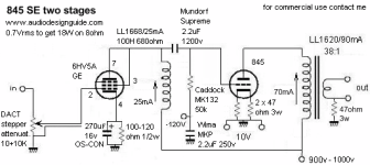
A schematic with a D3a is something I have not found around yet, interesting solution. I have the doubt why you posted a schematic with the 6hv5a as a driver (nice shcematic!).
Sorry, maybe it's a stupid question but why the input/interstage trafo should introduce higher noise and distortion?
The cost is not an issue here. I take into consideration that it will be an expensive project.I can't understand the people that have in mind an amp with a strange configuration, not easy and dangerous to build and are worry about the costs of the trafo?????????????????
Make a sense???
velleitario=unrealistic
Walter
I'm just trying to understand the best possible configuration.
As others have pointed out yes a 211 can drive an 845 but you still need something to drive the 211. Figure out what iron works best and go from there.
The cost is not an issue here. I take into consideration that it will be an expensive project.
I'm just trying to understand the best possible
To get the best configuration you need a proper test set to understand where you are going
Each of the esoteric strange configuration haven’ t had a proper diagrams of the test published
This is not to understand if they sound good but to certify that the configuration works properly in terms of power, Thd, FFT eyc
Walter
Thank you for your very complete consideration. Very intresting. This is also the reason why I'm looking for a schematic that is known working well. All the idea come from this post of THomas Mayer of some years ago:
https://www.diyaudio.com/community/threads/how-to-best-drive-an-845.184940/post-2500969
A schematic with a D3a is something I have not found around yet, interesting solution. I have the doubt why you posted a schematic with the 6hv5a as a driver (nice shcematic!).
Sorry, maybe it's a stupid question but why the input/interstage trafo should introduce higher noise and distortion?
The transformer doesn't make the noise. The 3rd tube makes the extra noise.
I have been looking for a schematic for you and I can't find anything useful for you. Everything I am seeing is either half complete, or junk.
As I continue to look for 845 schematics, you should really consider using a GM70 over an 845. It is a lot cheaper, sounds better in my personal opinion, needs less drive voltage, and can produce more power.
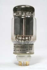
Some time ago I saw an 845 push-pull amplifier driven by a 6528 valve on the net. This valve has a very low internal impedance (245 ohms) and good gain with a mu of 9 (equal to an 801A). I am not able to do complicated calculations, but I like to imagine a possible 845 SE design where the 845 is driven by the 6528 via an interstage (a Lundahl LL1677-80mA designed to drive the 845 from a 300B). Also, if the total gain would not be sufficient there is always the possibility of adding (instead of a third stage) a 1:2 or 1:4 input transformer (Lundahl LL7902 or LL7902). Can anyone calculate how much oscillation the 6528 would be capable of as a driver?
Attachments
The transformer doesn't make the noise. The 3rd tube makes the extra noise.
I have been looking for a schematic for you and I can't find anything useful for you. Everything I am seeing is either half complete, or junk.
As I continue to look for 845 schematics, you should really consider using a GM70 over an 845. It is a lot cheaper, sounds better in my personal opinion, needs less drive voltage, and can produce more power.
I really thank you for all the help.
I'll start next week to put together a schematic. The idea to go with the GM70 is not bad actually. I don't know the tube and I have not seen it used a lot.
- Home
- Amplifiers
- Tubes / Valves
- Schematic for 845 amp with 211 driver