I've been working on a guitar amp over at TAG (The Amp Garage) and changed a design by Ken Fischer which is known as a "Trainwreck Liverpool"* to use Soviet tubes.
The Amp Garage :: View topic - Russian TrainWreck - Expresso Lite(Liverpool), Soviet tubes
I found that the background noise (hiss) was unacceptable unless I was very careful in my selection of the input tubes (originally 12AX7s which I replaced with 6N2Ps).
I first tried paralleling two triodes to reduce noise and this had limited success, in that it was still sensitive to tube selection.
In order to minimize the noise and make the circuitry less susceptible to "tube" to tube variations, I then tried a j-FET front end in conjunction with lower first and second stage gain which was quite successful.
Lastly I replaced the first triode stage with a small signal Pentode. which had phenomenal gain. I used Schade feedback to reduce the gain to a manageable level (Av70) along with reducing the second stage gain by a factor of two. The two in combination reduced the hiss to about 10mV which is quite acceptable for a guitar amp (although too much for an audiophile amp).
It appears to me that Schade feedback is classical feedback with the output impedance of the preceding stage as the input impedance in the classical equation:
A' = A *( Rfb/Rfb+Ri)
The Schade resistor can be tied to the gate of the Pentode if a coupling cap is used to isolate the DC voltage and prevent bias shift.
Therefore, the gain of a pentode with feedback Rf (ac coupled) and an input resistor Ri combines Ri plus the output impedance of the preceding stage Ri' for an overall gain of:
Vo= Vi*A*(Rfb/Rfb+(Ri+Ri')) Where Vi is the output of the preceding stage.
or, am I off in the weeds again?
*All rights reserved by the Fischer family
Please, call it "shunt feedback". "Shade" is a useless, arbitrary assignment, and not even consistent with anything else named (for instance, a guy named Thevenin devised the eponymous theorem).
For low noise, two cascaded (not -oded) triodes are better than one pentode.
The feedback equation you are looking for is:
Vo/Vin = G / (1 + G*H)
where
G = open loop gain of the amplifier
H = feedback voltage ratio
Vo/Vin = overall (system) gain
This also applies to linear, time-invariant systems, where G and H are a Laplace or Fourier domain transfer function.
Applying shunt feedback direct to a proceeding plate forms a voltage divider of H = Rp / (Rf + Rp) gain, where Rp is the total plate impedance (including plate resistor and grid leak).
Note that, for G >> H, this reduces to Vo/Vin = 1 / H, which is familiar from op-amps. A CCS-loaded pentode (mu ~ 4000), with feedback to reach an overall gain of 50 or so, would be an excellent case of this. Incidentially, such a stage would have vanishingly small distortion (< 0.1% at full output?), so naturally, the audiophools don't want you to know about it.
Tim
Schade feedback is feedback proposed by Schade to correct 6L6 tube for SE usage.
The problem with parallel (shunt) feedback in low level amplifiers is their input resistance. For less noises you want lower values of resistors. For high input resistance you want higher values of resistors.
Probably, it will work well if you use it with SRPP (for the example, Michael Koster's post in recent Gyrator thread)
I was considering shunt feedback to reduce the output impedance of my oscilloscope stages. Should extend bandwidth better than Rp alone (which requires high current tubes and lots of extra dissipation to accommodate).
More important than noise, large resistors would cause excessive capacitive loading, screwing up bandwidth. Scope circuits require low impedances and high linearity. Open loop impedances are minimized by choice of high Gm, moderate-current tubes (Tektronix was fond of 6DJ8 and 6DK6), and NFB. Cathode degeneration is easiest, but I'm thinking shunt would be advantageous.
Incidentially, 100kohms makes 5.75 uV over the audio band, which is a good -45dB from microphone levels (~1mV). Tubes are pretty noisy in comparison, so don't worry too much about noise from feedback resistors.
Input impedance is a big concern for input stages, and either a conventional stage, or a buffer (CF?) would be a reasonable choice to fix this. (Incidentially, if you use a CF, don't forget the series resistor in the feedback path, otherwise your feedback resistor will try working into the CF's output impedance, which isn't going to work well!)
Tim
So-called Schade feedback seems to be coming as fashionable as SRPP etc. He simply applied the old "anode follower" technique to an output stage. That is basically it. Now, as discussed in another thread, "anode follower" is a daft name for what is essentially Miller-style feedback (think inverting opamp) but it is preferable to "Schade". "Anode follower" is what the textbooks call it, so we should do the same.
The weakness of the anode follower is that it either requires a big input resistor (which can be noisy, and interacts with Miller capacitance) or it relies on the output impedance of the previous stage (as the OP thought) and so introduces a new source of distortion as output impedance can be more non-linear than voltage gain.
The weakness of the anode follower is that it either requires a big input resistor (which can be noisy, and interacts with Miller capacitance) or it relies on the output impedance of the previous stage (as the OP thought) and so introduces a new source of distortion as output impedance can be more non-linear than voltage gain.
Schade = sameoldsameold anode follower for sure.
But Schade's Fig35 proved that local feedback from
plate to grid is what gave a Triode Mu to begin with.
What the screen taketh away, Schade givith back
in spades! Or Mu or whatever...
Some things called Schade today, deviate pretty far
from any of his schematics. But what really matters
is wether said design adheres to principals of Fig35.
I'd accuse the worst pretenders to Schade approach
GNF. Oft forgotting the key word is "Local".
Last edited:
There isn't a good name for it. I think we on this forum started calling it "Schade" about the time I started a thread titled "What if O. H. Schade had MOSFETs?".
I've started calling it "stage local plate-to-grid feedback" because that's what it is. Other techniques like feedback to the cathode are different over the wide range of operating conditions (how to get a D3a stage to input 150V P-P signal without an attenuator? good luck using CFB...)
Usually, an input resistor is addeed to the output impedance of the preceeding stage to stabilize the gain and provide a finite impedance for the preceding stage to work into.
There are lots of ways around the input impedance problem. one way is to use a pentode or MOSFET as the first stage and load it with the plate feedback current of the next stage. Examples abound. Another way is to use a mu-follower etc. to buffer the drive to the input resistor. Also, some applications are happy with relatively low impedance input circuits. The practical range in my experience is from 1K to 10K ohms as an input resistor, and about the same equivalent load if using the technique of feedback to the driver plate (drain). Schade's original circuit used a coupling transformer to sum the feedback from the plate, thus avoiding the impedance issue.
Something hot mentioned is that the gm of the tube is preserved, i.e. if you have a 10 ma/v gm pentode you can adjust the feedback to get any ratio of mu and rp that preserves the 10,000 gm. For example, you could design for mu of 10 and Rp of 1000 ohms, or mu of 5 anf Rp of 500 ohms. So of course when using the voltage divider feedback you need input voltage to drive the feedback network accordingly. Using the 2 stage MOSFET or pentode (or even a high Rp triode) driver circuit the needed drive voltage is minimal; the feedback is current based over the gm of the driver.
The noise of the stage is a function of it's input resistance. The input resistance is limited by plate-grid capacitance and desired upper Fc and would not practically be as high as 100K in most circuits. More like 1K to 10K inmy experience.
5.75 uV self noise is about 20 dB too high for a 1mV sensitivity microphone in studio use. Luckily, microphones like 1000 ohms load or so, which reduces the resistor noise to ~600 nV. Tubes can be this quiet or even better (D3a is 65 ohms ENR in triode connection).
But I don't see though how local feedback would extend bandwidth. If you add too much input resistance it could reduce the upper Fc due to Miller effect. I have not had a problem using even triodes up to about 10K grid resistance in these circuits.
Cheers,
Michael
And then there's the new kid on the block: "Magic" Schade feedbacks or Output Voltage plus Differential Current Sensed Series Feedbacks. OV+DCSSFdbk or "Magic" for short. Gets rid of crossover distortion for class AB. (requires some overlap in output stage conduction, driver is class A differential)
European Triode Festival and Crossover Notch Distortion and New OTL Design
(2nd diagram up from bottom)
Hope it's OK to attach the diagram from Tubecad, Dec 20, 2006.
And then RCA RC-30 Handbook, page 696, attached.
Here the cathode feedbacks to the driver are the equivalent, except would need a CCS tail on the driver. The current sense resistors are implicit in the DC resistance of the primary windings.
edited to remove distortions!
Attachments
Last edited:
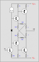
According to what we learned in Russia, it is "Parallel Feedback By Voltage". No confusion is possible: a fraction of output voltage is applied in parallel with input signal.
When people don't have systematic academic education they tend to view examples in popular books and magazines as revelations, attributing them to authors of books and articles, calling them by their names.
Here again is a picture I drew long time ago for students:

When people don't have systematic academic education they tend to view examples in popular books and magazines as revelations, attributing them to authors of books and articles, calling them by their names.
Here again is a picture I drew long time ago for students:
But I don't see though how local feedback would extend bandwidth. If you add too much input resistance it could reduce the upper Fc due to Miller effect. I have not had a problem using even triodes up to about 10K grid resistance in these circuits.
If you just add a resistor in series with the grid, it will directly cut the high frequency response since it forms a low pass filter with Miller capacitance. However, when the feedback resistor is also added from anode to grid, the situation changes. The smaller the anode-to-grid resistor is, the lower the gain is, but also with the same the high frequency response will be extended. And distortion reduced, input impedance reduced, output impedance reduced, etc.etc....
I think Michael probably was referring to the series resistor from the previous stage (maybe a triode, so needs this to establish a constant source R), not the grid stopper R. Does seem like one could skip the grid stopper here though.
If you just add a resistor in series with the grid, it will directly cut the high frequency response since it forms a low pass filter with Miller capacitance. However, when the feedback resistor is also added from anode to grid, the situation changes. The smaller the anode-to-grid resistor is, the lower the gain is, but also with the same the high frequency response will be extended. And distortion reduced, input impedance reduced, output impedance reduced, etc.etc....
Why would you add a large series resistor to the grid if not for the purpose of the feedback divider? Compared to a circuit using only a grid stopper, how can plate feedback with an added input resistor extend the frequency response? Also not sure about eliminating the grid stopper unless the input and FB resistors are right on the socket pin, or at least some portion of them.
My experience with these stages is that even at relatively low gain using a lot of feedback you don't get any better upper Fc than a full gain circuit with a low value grid stopper and careful layout.
At typical circuit values assuming a D3a in triode mode (Cgp 2.7 pF) and 5K-10K ohm input resistance, stage gain about 40, the upper Fc is on the order of 100-200 KHz. I think you can do much better with a low value grid stopper and no feedback, but for audio it's sufficient.
Cheers,
Michael
According to what we learned in Russia, it is "Parallel Feedback By Voltage". No confusion is possible: a fraction of output voltage is applied in parallel with input signal.
I'm confused. Two voltage sources in parallel?
The Schade paper shows two voltage sources, the input signal and the divided down output signal, summed by using an interstage transformer sitting on the feedback divider. I would call this a series connection.
Attachments
I'm confused. Two voltage sources in parallel?
The Schade paper shows two voltage sources, the input signal and the divided down output signal, summed by using an interstage transformer sitting on the feedback divider. I would call this a series connection.
Effectively it is in parallel, but summed on grids, with transformer windings in series.
Wow! I'm really surprised to see the responses this has illicited.
Ok, I'll adopt the nomenclature "Shunt Feedback" if you prefer, but I'm not giving up "Thevenin's Equivalent".
Sorry, I gave up Cycles per Second in lieu of Hertz, and I'm not going any further.
Next you will be wanting me to concede that current flows from Positive to Negative.
Bah Humbug!
Back to the core of the question at hand, from everything posted here I still feel that what O.H.Schade described is now classical feedback with an input resistance and a feedback resistance. The equations can be derived if the Thevenin's equivalent of the preceding stage is used as the input to the gain stage with feedback.
The output impedance (including next stage grid resistor) becomes the input impedance of the feedback equation.
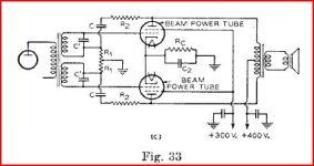
This to me looks like fig 33b for single ended or 33C for PP.
This is the central premise of what I was trying to convey.
Ok, I'll adopt the nomenclature "Shunt Feedback" if you prefer, but I'm not giving up "Thevenin's Equivalent".
Sorry, I gave up Cycles per Second in lieu of Hertz, and I'm not going any further.
Next you will be wanting me to concede that current flows from Positive to Negative.
Bah Humbug!
Back to the core of the question at hand, from everything posted here I still feel that what O.H.Schade described is now classical feedback with an input resistance and a feedback resistance. The equations can be derived if the Thevenin's equivalent of the preceding stage is used as the input to the gain stage with feedback.
The output impedance (including next stage grid resistor) becomes the input impedance of the feedback equation.
This to me looks like fig 33b for single ended or 33C for PP.
This is the central premise of what I was trying to convey.
Not so fast...
The circuit in 33(c) doesn't depend on the output impedance of the preceding stage to determine the feedback ratio. It subtracts the feedback voltage from the drive voltage at the node where the voltage divider tap connects to the coupling transformer winding. The feedback induces no current in the input circuit. This one generally requires a lot of drive voltage.
There are at least two other ways to get feedback from plate to grid. One of these is with an input resistance and a feedback resistance forming a divider, the tap of which is connected to the grid. In this circuit, the output impedance of the preceding stage is added to the input resistance. If there is a grid resistor, it's bootstrapped by the feedback and only a fraction of it's value contributes. This type generally needs a lower drive impedance and substantial drive voltage (to drive a pentode power amp stage with low output impedance).
The third topology I can think of is perhaps a special case of the second, where the driver dynamic load is mostly made up of the current through the feedback resistor. Examples are the Tabor from Gary Pimm and the DCPP amp from Pete Millett. The driver pentode acts as voltage-to-current converter loaded by the feedback resistors. Thus the grid-plate voltage of the output stage is a function of the input voltage to the driver pentode stage. The RH84 etc. do this using a triode driver. That's actually not so bad because the triode's Ri as well as any grid resistor or driver plate load resistor are bootstrapped by the feedback. This type is to me most efficient in terms of overall power gain for the circuit effort; the input pentode only needs to swing the output pentode's grid voltage. As a plus it offers the potential to get differential feedback in push-pull mode to smooth out the crossover distortion (or operate closer to class B). This one also produces the lowest effective plate resistance, close to 1/gm.
Last edited:
Did a comparision sim quite a while ago in another thread.
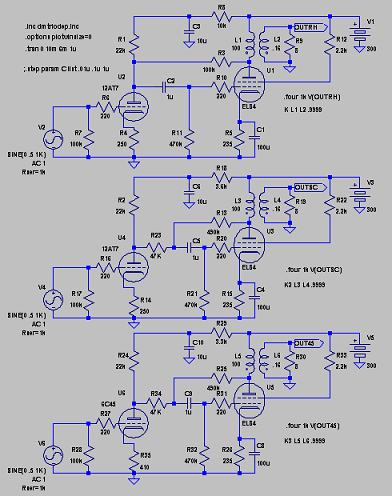
This showed a reduction in distortion when going the route of the lower two to half of the upper. Yet to be proven IRL.
In another thread I showed a 12ax7 buffered with a MOSFET SF also showed promising results using the "lower" method.
The 12AT17 has a Ri of ca 20k in the upper version while the idel driver, pentode, has infinite and can be looked upon as a current source.
In the sand-world the most wellknown application of "Schade" is NP´s Zen.
But hasn´t all of this been covered in many threads before???????
Last edited:
Not so fast...
The circuit in 33(c) doesn't depend on the output impedance of the preceding stage to determine the feedback ratio. It subtracts the feedback voltage from the drive voltage at the node where the voltage divider tap connects to the coupling transformer winding. The feedback induces no current in the input circuit. This one generally requires a lot of drive voltage.
Actually, load of the preceding stage on the grid's impedance is higher when feedback is applied. Let it be very high impedance, mostly capacitive, but anyway it is higher.
...how can plate feedback with an added input resistor extend the frequency response?
Below is the figure of the results achieved with shunt feedback connection. Different traces represent different values of feedback resistor connected from anode to grid. The series resistor at the grid is held constant.
The topmost trace represent largest feedback resistor. The gain is 39 dB and fc (-3 dB) = 8 kHz. The lowes trace represent smallest series resistor. The gain is reduced 5 dB (to 34 dB) and fc (-3 dB) is extended to 14,4 kHz.
How this happens ? There are many good books to explain this so well that I do not even try put this in words.
Photo here:
An externally hosted image should be here but it was not working when we last tested it.
- Status
- Not open for further replies.
- Home
- Amplifiers
- Tubes / Valves
- Schade Feedback