Yeah, I've got some prototyping chassis's laying around here too. I do think this new differential variant deserves a trial. I've never seen anything like it. Looks good in theory anyway. Easy enough to try as a driver stage.
One thing that has me wondering lately though. Allen Wright came out with those CCS tailed class A output amplifiers that get rave reviews. Now the theory says that kind of setup is very 3rd harmonic distorting. Compressive for sure. But it occurred to me one day, that all this talk of transparent detail may be just that. The loud stuff is quieted down, so the soft stuff comes through more clearly. Another euphonic distortion machine, but 3rd harmonic compressive this time. This audio search for "fidelity" is hopeless..... You just have to build it the way you want it, or put some front panel knobs on to adjust the 2nd and 3rd harmonic distortion to taste. One can design the most linear amp imaginable, but nobody really wants it out there. They just claim to.
One thing that has me wondering lately though. Allen Wright came out with those CCS tailed class A output amplifiers that get rave reviews. Now the theory says that kind of setup is very 3rd harmonic distorting. Compressive for sure. But it occurred to me one day, that all this talk of transparent detail may be just that. The loud stuff is quieted down, so the soft stuff comes through more clearly. Another euphonic distortion machine, but 3rd harmonic compressive this time. This audio search for "fidelity" is hopeless..... You just have to build it the way you want it, or put some front panel knobs on to adjust the 2nd and 3rd harmonic distortion to taste. One can design the most linear amp imaginable, but nobody really wants it out there. They just claim to.
Last edited:
Well one thing is for sure, a high gm pentode with a little plate-grid feedback makes a better triode than a triode does. 😀 I love my pentode amps.
smoking-amp - Do you have some curve traces for the variable Schade feedback configuration? Do they look like triode curves?
I'll get some Schade "triode" traces here soon. Have to get set up.
---------------
I've been doing a little simplified math modeling of the screen grid servo'd "differential" stage from earlier above, and it is requiring wild voltage swings on the screen grid to keep the current constant. So that's not going to work in practice. It may still be possible to use the "magic" complementary sum of gm versus Vg1 curves with some other approach:
Looking at the usual CCS'd tail differential stage, the tail voltage increases when maximum complementary Vg1 are present (max signal input), this is to get the low gm side to turn off faster, to provide current for the high gm side (the gm sum would naturally prefer to draw more combined current there, if it could). But that is also when the gm sum starts to droop under CCS conditions, causing the 3rd harmonic distortion in the outputs. If the tail impedance were lower there, it would self correct by drawing more current, boosting the gm sum slightly.
The M. V. Kiebert paper addresses this issue by using a selected R in the tail, so total current increases slightly at max signal, bringing up the combined gm slightly. That fix can ideally be tuned for 3rd harmonic null, and for improved, but not zero, higher odd harmonics. In practice, with real tubes, it only works over a limited signal range, even for 3rd harmonic.
Obviously there is some mistracking involved, from using just a linear R for the tail.
Looking at the behavior of the tubes, each tube gm is (for our selected operating point) varying approx. linearly with grid voltage (the linear slope section of the gm curves for gm versus Vg1, this is the same as 2.0 power law for V to I, the gm power law is just 1.0 less, due to being the derivative). Equivalent cathode impedance would be 1/gm, so the R tail should likely track in this way too.
(although, one tube is increasing in gm and the other decreasing in gm when a signal is applied, the sum is probably some other reduced power law. It is possible that we are just requiring some odd curve fitting here to get the correct tail impedance variation or "curvature".)
Now a damper diode gives 3/2 power law V to I, not quite right since "1/gm" or conductance is then 3/2 -1 = 1/2 power law.
A Mosfet however operates with 2.0 power law V to I. So if we make a "diode" from a Mosfet, it will have a 1.0 power law for gm, just right (well, maybe).
We also have to get the numerical nominal impedance correct as well, probably something like (1/gm || 1/gm) or 2/gm from the tubes.
The typical Mosfet "diode" will be too low an impedance, so we use a high R divider from the Mosfet drain to source to attenuate the controlling gate voltage.
(Putting a degeneration R in the source would mess up the 2.0 V to I power law. However, if it turns out that we really need something less than 2.0, putting in some source degeration would allow us to tune the V to I power law between 2 and 1 (and the effective gm power law between 1 and 0 (or constant)). Maybe someone could simulate a differential tube stage, with a special adjustable Spice model V to I power law R tail, to see what works best.)
So the new setup looks like this (possibly with a Mosfet Source degeneration R added if we have to adjust the correction "curvature"):
Attachments
Last edited:
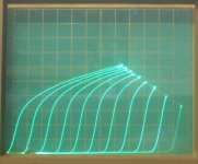
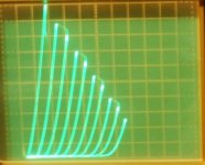
Here are some curve traces for a 12HL7 beam pentode (or beam tetrode for the finicky). This tube does not have aligned g2/g1 grid wires, but does have a frame grid for g1.
1st pic is in "pseudo" triode mode (screen to plate): 0.5 V/step on g1, 5 mA/div vertical, 20V/div horizontal.
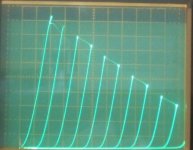
2nd is in "pseudo" triode mode: 1 V/step g1, 10 mA/div vert., 50V/div horiz.
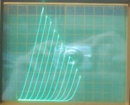
3rd is in Schade mode with 100K and 22 uF cap feedback from plate, and 22K from tracer g1 stepper. 2.5 V/step from tracer, 5 mA/div vert. and 10 V/div horiz. 100 V on g2
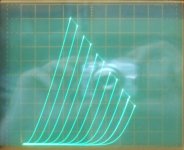
4th is in Schade mode, everything the same 100K, 22uF and 22K, same 2.5V/S, 5mA/div, 10V/div, but 50 V on g2 this time. Clearly you need enough Vg2 for the peak current needed.
As you can see, the Schade mode is super linear. However, the internal Mu of the 12HL7 is around 25 (in the "pseudo" triode mode curve sets), while the Schade mode configuration here is around 4.54 Mu, so the Schade has got 5.5 times as much N Fdbk here. So one would expect it to be pretty darn good. I don't think I've seen any real triodes this good!
-----------------------------------------------------------------
One thing occurs to me about this Schade mode, it is using the same grid for control and feedback. While "real" triodes and Psuedo triodes are using the plate or screen grid for N Fdbk. The power law for grid 1 varies with current between 3.0 or so and 1.1 typically. While the power law for g2 and plates is typically fairly consistent around 1.4 to 1.5.
The more "linear" g2 and plate (at 1.4 or 1.5 power law, but preferably we would like it at 1.0) does give the "real" and the "psuedo" triodes some advantage for the same amount of N feedback over the Schade. (the N Fdbk gets less distorted through a 1.4 PL grid than through a 2.+ PL grid))
But on the other hand, the pentodes typically have more grid 1 gm, which if degenerated down to the lower gm level found in typical triodes, that probably would bring the grid 1 power law down to a 1.4 level or so too. So we really have a close horse race as to which might be more linear. Certainly frame grids will take the lead for any tube type, as the 12HL7 clearly does here.
Another thing I notice, is that the Schaded pentode can use an elevated screen voltage, so this can be driven down to lower plate voltages than a triode. This makes for a more efficient output stage. Also makes for a lower Rp to do that. So in this light, I would say the Schade mode is the clear winner.
-------------------------------------------------------------------
I think I will trace a horizontal output TV tube in Schade next.
----------------------
1st pic is in "pseudo" triode mode (screen to plate): 0.5 V/step on g1, 5 mA/div vertical, 20V/div horizontal.
2nd is in "pseudo" triode mode: 1 V/step g1, 10 mA/div vert., 50V/div horiz.
3rd is in Schade mode with 100K and 22 uF cap feedback from plate, and 22K from tracer g1 stepper. 2.5 V/step from tracer, 5 mA/div vert. and 10 V/div horiz. 100 V on g2
4th is in Schade mode, everything the same 100K, 22uF and 22K, same 2.5V/S, 5mA/div, 10V/div, but 50 V on g2 this time. Clearly you need enough Vg2 for the peak current needed.
As you can see, the Schade mode is super linear. However, the internal Mu of the 12HL7 is around 25 (in the "pseudo" triode mode curve sets), while the Schade mode configuration here is around 4.54 Mu, so the Schade has got 5.5 times as much N Fdbk here. So one would expect it to be pretty darn good. I don't think I've seen any real triodes this good!
-----------------------------------------------------------------
One thing occurs to me about this Schade mode, it is using the same grid for control and feedback. While "real" triodes and Psuedo triodes are using the plate or screen grid for N Fdbk. The power law for grid 1 varies with current between 3.0 or so and 1.1 typically. While the power law for g2 and plates is typically fairly consistent around 1.4 to 1.5.
The more "linear" g2 and plate (at 1.4 or 1.5 power law, but preferably we would like it at 1.0) does give the "real" and the "psuedo" triodes some advantage for the same amount of N feedback over the Schade. (the N Fdbk gets less distorted through a 1.4 PL grid than through a 2.+ PL grid))
But on the other hand, the pentodes typically have more grid 1 gm, which if degenerated down to the lower gm level found in typical triodes, that probably would bring the grid 1 power law down to a 1.4 level or so too. So we really have a close horse race as to which might be more linear. Certainly frame grids will take the lead for any tube type, as the 12HL7 clearly does here.
Another thing I notice, is that the Schaded pentode can use an elevated screen voltage, so this can be driven down to lower plate voltages than a triode. This makes for a more efficient output stage. Also makes for a lower Rp to do that. So in this light, I would say the Schade mode is the clear winner.
-------------------------------------------------------------------
I think I will trace a horizontal output TV tube in Schade next.
----------------------
Attachments
Last edited:
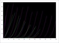
I think I have shared this with you before, probably multiple times, but I followed the procedure in Schade's "Beam Power Tubes" paper for plotting plate-grid feedback curves for 20% feedback on a KT88 and plotted this against KT88 pseudotriode curves and 300B curves, all on the same scale so that they can be easily compared.
Cyan is KT88 pseudotriode, mu is about 8. Yellow is 300B, mu is about 3.8. Pink is KT88 with plate-grid feedback and mu of about 5.
KT88 with plate-grid feedback can outperform a 300B every which way by having a lower rp, better linearity, and higher gain. (Oh, and they're much cheaper, too)
Ever since then, I have been using high-gm beam tubes as output devices and I no longer dream of building a 300B amp.
Attachments
Man, those 12HL7 curves with feedback are just beautiful.
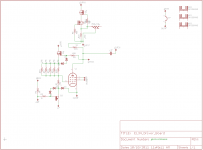
I've been meaning to do an experiment. I want to make a PCB to turn an EL34 (a pretty inexpensive and easy to find tube) into something that can develop a really large voltage swing at low distortion. Something to drive cathode follower output stages and the like.
I did the schematic entry and layout but haven't had it made yet, but this is what I had in mind.(I still need to fix it so that the output comes from the source of the n-channel fet follower and not the anode) I'm hoping it would perform better than the 841-based driver I made for my Unity-Coupled amp.
Attachments
Sorry, I just realized that I used enhancement mode symbols for depletion mode fets in the CCS. I was too lazy to redraw new symbols.
Edit: And I have nonsensical values in the feedback network.
Edit: And I have nonsensical values in the feedback network.
Last edited:
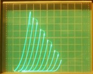
Here are some traces for 36MC6 in "pseudo" triode and Schade mode.
Both are 50 mA/div Vertical, 50V/div Horizontal, and 7.5 V/step, with 82 V on g2 for the Schade version (2nd pic). Internal tube Mu is 4 and the Schade Mu is around 4.54 again (same 100K with 20 uF cap plate Fdbk and 22K grid as before), so comparable Fdbk gains.
Sorry for the poor focusing, my Fuji camera is refusing to focus on the tracer screen lately, took almost 20 tries to get these pics. Maybe tomorrow in the daylight it will work better. The curve tracer has got one selector switch that is acting up too. My old Kodak DVC323 camera used to take perfect pictures every time, but I can't find the software for it online anymore after changing operating systems on the PC. (I have the driver, missing the application softw.)
Attachments
Last edited:
I just noticed that the Schade curves (above, right side) for the 36MC6 are showing higher Rp than the triode curves. And the triode curves are reaching higher current peaks too.
I think this is just a matter of adjusting the screen grid voltage for the Schade case, when the screen voltage is adequate to get the same peak plate currents, the Rp's look the same. I'll have to watch out for that when plotting curves to compare.
It does look like the Schade curves are more equally spaced than the triode curves, and have less tilt over at high Vp than the triode curves (for the same effective Mu and gm). Probably because the Schade case uses the same electrode for both input and N Fdbk, while the triode case is using two electrodes with different power laws.
While having breakfast this morning, I was circuit dreaming a bit, and realized that the secret to super Schade curves is super high gm. So I have come up with a simple "gm booster" circuit to fit onto a tube now. Hope the curve tracer holds up for a while yet. So much stuff to test.
Last edited:
In post #27, the data from SpreadSpectrum shows that the curves near Eg1=0V are bunched up, which also shows up in my SPICE sims as well, but there does not seem to be such bunching-up effect on your curve traced scopeshots, what might account for the difference?
I have been seeing the same thing actually. Since my voltage readout for the grid1 is calibrated to the input side of the V to I input resistor, I've just been adjusting the tracer bias until I just got rid of the squeezed bunch. (I was assuming the grid had gone positive and was consuming the input signal) So the 1st (left) traces are likely beginning at some negative grid voltage already.
I guess at zero bias the small grid current initially "eats" the input signal current, but clears up after a going Volt or so negative.
I guess at zero bias the small grid current initially "eats" the input signal current, but clears up after a going Volt or so negative.
Last edited:
In post #27, the data from SpreadSpectrum shows that the curves near Eg1=0V are bunched up, which also shows up in my SPICE sims as well, but there does not seem to be such bunching-up effect on your curve traced scopeshots, what might account for the difference?
It is because, despite all of the feedback we are still operating as a pentode here.
So first, we can look at the Vg1 = 0 line of the *pentode* characteristics and we can know that:
1) We will not be able to go out of that area under that curve *above the knee* without providing Vg1 current.
2) If we try to go out from under the Vg1 = 0 curve *below the knee* we will get nowhere. At that point, grids are swallowing up the vast majority of additional electrons flowing from the cathode and they don't make it to the plate. We can't go to that area and if we try really hard, we just melt grids. We have reached saturation and feedback won't help us get past it.
So the curves bunch up a bit as we get close to the saturation line.
Ahhh, of course.
So actually my plots are starting at some positive plate voltage (like +50 V maybe) instead of 0 Vp.
I just tweaked the position knobs until it all was centered on the screen.
So one needs to avoid too low a plate V or one melts the grids here. Mainly the screen grid. Maybe a good stopper R on the grid 2 will suffice. (Actually, the tracer leads I'm using have a 120 Ohm stopper resistor in the grid 2 lead already. There is also an adjustable current limiter on the screen V supply.)
Last edited:
I had a board made for output tubes of the 6L6/EL34 pinout and I included a simple mosfet regulator for the screen, which can be just powered from the main B+. I put a current-limiter BJT to pull the gate of the mosfet down if screen current gets too far out of control (I set it at 75mA). If I drive a pentode really hard with this screen supply, the output looks like a peak with a nicely rounded little volcano crater at the top. It reaches a point where driving it harder actually reduces output because the screen is sagging, pulling that Vg = 0 knee down further. I left capacitors out of the circuit, so it recovers instantaneously.
Incidentally, I used that same board for my Unity-Coupled amp and I tied the screen supply positive to the opposite tube plate rather than tying the screen there directly, so now I have my output tubes running at reduced screen voltage and a safety current limit as well. Hopefully I get a nice long life out of the output tubes.
But yeah, in a curve tracer, I would definitely have some sort of current limit set since it would be really easy to get in a situation with some huge screen currents. I am apparently able to hit 75mA peaks relatively easily in real amp conditions. I also have 100 Ohms in series with the output of the regulator.
Thanks for the clarifications, guys. Now it makes more sense why the curves bunch up with Schade feedback... I am still wondering if the same thing happens with CFB? The Ep-Ip characteristic that I have seen for CFB looked more like UL and no curve bunching was evident... can't find the image now, urgh...
- Status
- Not open for further replies.
- Home
- Amplifiers
- Tubes / Valves
- Schade and CFB exactly equivalent