package arrived
Bob, Thanks for the goodies which have arrived, AOK.
Jens, Thank You...for providing such an elegant PS solution.
Bob, Thanks for the goodies which have arrived, AOK.
Jens, Thank You...for providing such an elegant PS solution.
Question:
Substitutes...
I need to find a substitute for the "power" - transistors, what parameters should I look for?
Arne K
Substitutes...
I need to find a substitute for the "power" - transistors, what parameters should I look for?
Arne K
Hi Andrew. Schottkys are much faster in switching on and off and generate far less noise (and spikes when used as a rectifier)than a semiconductor diode.
I most cases it is found that a capacitor in parallel with a schottky is not needed and sometimes even detremental.
A real snubber (R/C combination) is always better than just a Capacitor but you have tune it carefully to get the best results.
If you don't have noise at the output of your PSU why bother.
Don't try to fix something that is working properly.
Hi,
I just wish there was an easy and cheap way to "tune" the RC snubber to each transformer.
Can anyone help?
The idea of measuring the transformer and doing all those calcs is getting to me.
I just wish there was an easy and cheap way to "tune" the RC snubber to each transformer.
Can anyone help?
The idea of measuring the transformer and doing all those calcs is getting to me.
Re: Question:
current rating >1A
fits space
with the darlington connected driver the gain is relatively unimprotant.
similar speed
MJE15030/31 should work if you can get those.
Cobra2 said:Substitutes...
I need to find a substitute for the "power" - transistors, what parameters should I look for?
Arne K
current rating >1A
fits space
with the darlington connected driver the gain is relatively unimprotant.
similar speed
MJE15030/31 should work if you can get those.
I did hook up the old scope to do some measurements.
Regulator adjusted at 15,00 V load 200mA.
When using a 20Vac 80VA tranny i got excactly 15,00 Volt load or no load.When heating up the voltage dropped 10mV.
With my old scope i couldn't find any 100Hz ripple at the output.
I did find a 5MHz ripple of 1mV PP. I'm not shure where it's coming from.I used shielded test leads.
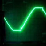
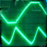
The input AC just showed a just visible flattening of the sine wave.
Lowering the input voltage to 14.5Vac had no affect on the output voltage.The 5MHz ripple increased to 2mV PP.
The input AC showed clear flattening of the sine wave and some switching artefacts.Couldn't get a clearer picture due to reflections etc.
Regulator adjusted at 15,00 V load 200mA.
When using a 20Vac 80VA tranny i got excactly 15,00 Volt load or no load.When heating up the voltage dropped 10mV.
With my old scope i couldn't find any 100Hz ripple at the output.
I did find a 5MHz ripple of 1mV PP. I'm not shure where it's coming from.I used shielded test leads.
The input AC just showed a just visible flattening of the sine wave.
Lowering the input voltage to 14.5Vac had no affect on the output voltage.The 5MHz ripple increased to 2mV PP.
The input AC showed clear flattening of the sine wave and some switching artefacts.Couldn't get a clearer picture due to reflections etc.
Attachments
Hi Kro,
Try using a really short gnd wire when you measure. This will get you a small loop and less noise will be injected into the probe/scope. The result should be a clearer measurement.
\Jens
Try using a really short gnd wire when you measure. This will get you a small loop and less noise will be injected into the probe/scope. The result should be a clearer measurement.
\Jens
Hi Kro,
just to clarify.
The 20Vac power input reduced to 14.5Vac has caused the HiFreq to double from 1mV to 2mV (seems almost inconsequential) and causes that very clear flattening of the AC input waveform that you posted.
That posted waveform is what exactly? The low voltage AC input to the rectifiers?
Seems almost like a dead short on the transformer when the rectifier conducts. Then the sudden drop in voltage as the rectifiers turn off.
Could you post the post rectifier waveform for comparison (preferably in phase with the input)
Kro,
Do you have differential probes or has your scope seperate grounds for the two channels?
There is no direct connection from the AC side of the bridge to ground on the board, so I don't fully understand your measurement setup.
\Jens
Do you have differential probes or has your scope seperate grounds for the two channels?
There is no direct connection from the AC side of the bridge to ground on the board, so I don't fully understand your measurement setup.
\Jens
Jens, i used just one ground.(negative side of the rectifier).
I was aware that i couldn't use both ground because it creates a shortcut over the bridge.
I tried separate measurements on one channel.First before the bridge and than after the bridge and the results are excactly the same.
Kees.
I was aware that i couldn't use both ground because it creates a shortcut over the bridge.
I tried separate measurements on one channel.First before the bridge and than after the bridge and the results are excactly the same.
Kees.
Kees,
Didn't you test with a DC supply once? Does the supply show any 5 MHz with DC input?
How is your load connected? Is there anything around that may be radiating 5 MHz?
My supplies showed nothing higher than 300 kHz under any conditions. I don't think Jens say anything as high as you do, either.
Didn't you test with a DC supply once? Does the supply show any 5 MHz with DC input?
How is your load connected? Is there anything around that may be radiating 5 MHz?
My supplies showed nothing higher than 300 kHz under any conditions. I don't think Jens say anything as high as you do, either.
I will try again with the DC supply.
The load is connected via two single 30 cm wires.
I don't know where i can pick up a 5 Mhz signal .There is no equipment in close vincinity, just some fluoresent lighting.
It seems to be an almost pure sine wave.
I am no to worried about it though. It is afterall only 1-2 mV.
At that level and frequency my old scope has some difficulty triggering on it.
Kees.
Kees,
Your load leads are about the same as what i measured with.
Are your AC input leads fairly short? (15 cm or so?) Jens and I both found longer leads seemed to enable ringing.
Bob
Your load leads are about the same as what i measured with.
Are your AC input leads fairly short? (15 cm or so?) Jens and I both found longer leads seemed to enable ringing.
Bob
My tranny is directly wired to the PSU board. About 20 cm twisted solid copper wire 1sq. mm
Kees.
Kees.
I hooked up the DC supply with the same results,the amplitude fluxtuated a little.
I examined the signal closer and it seems like a approx. 5.5MHz signal modulated with a 125-130 kHz signal.(my scope isn't that accurate below 1uS.
I switched off the fluorescent, changed wires to R59B coax and even grounded the scope to the mains earth connection.(which i normally never do)
Only the amplitude changed a little.
I think i pick up a signal somewhere but i don't know how.
As i said,i don't worry about it.
Kees.
Thanks for your thoroughness, Kees. Perhaps there's a transmitter closer than you think. You might try increasing C7, the 100 pF cap to see if that helps, at the expense of some speed.
I'll feel better if we get a few more people posting that they have clean output. I've got three 15V supplies built and all behave as I described earlier.
Has anyone else stuck a scope on their supply?
I'll feel better if we get a few more people posting that they have clean output. I've got three 15V supplies built and all behave as I described earlier.
Has anyone else stuck a scope on their supply?
Do I understand correctly that both grounds for +15V and -15V need to be seperate throughout the circuit, including whatever comes next?
Is there a clear performance reason for choosing seperate grounds? In other words, will using a centre tapped transformer with the necessary modifications as mentioned before be detrimentall to the performance?
Is there a clear performance reason for choosing seperate grounds? In other words, will using a centre tapped transformer with the necessary modifications as mentioned before be detrimentall to the performance?
Hans, Sorry about any confusion. The grounds were kept separate for flexibility - you can use the two supplies completely independently, or even cut them apart.
There is no reason to keep them completely separate after the supply except possibly to the extent that each ground should have its own lead to the power star ground.
I don't think that there will be any performance penalty to using a center tapped transformer, but I have not built it that way (yet).
Edit: Be sure to omit the diodes as described earlier to avoid shorting the transformer.
- Status
- Not open for further replies.
- Home
- Group Buys
- Scalable PSU/regulator GB