Finished Stereo SC200
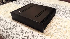
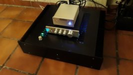
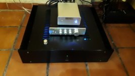
Finally finished the SC200 in stereo. The case is a bit on the large size but its all there was at the time.
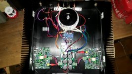
I think I may have made a mistake with the transformer placement and was worried how it would affect the sound being right up against the speaker wires.
I tried to be tidy with the wiring but no chance. Wires all over the place and not sure about wire twisting but I guess I was lucky; no hum whatsoever. It sounds like a dream into 4 Ohm Uni-Fi UB5s; crystal clear and precise.
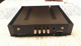
I had to put the 10k Stepped attenuator in the top cover as the front plate was way too thick for the thread.
Any constructive criticism/layout comments are more than welcome!
Finally finished the SC200 in stereo. The case is a bit on the large size but its all there was at the time.
I think I may have made a mistake with the transformer placement and was worried how it would affect the sound being right up against the speaker wires.
I tried to be tidy with the wiring but no chance. Wires all over the place and not sure about wire twisting but I guess I was lucky; no hum whatsoever. It sounds like a dream into 4 Ohm Uni-Fi UB5s; crystal clear and precise.
I had to put the 10k Stepped attenuator in the top cover as the front plate was way too thick for the thread.
Any constructive criticism/layout comments are more than welcome!
Attachments
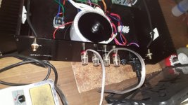
You use two heatsinks for each side but on the only one are power transistors. It's hard to see - did you jointed the heatsinks for better heat flow?
The case came with four heatsinks. I never realized they were split when I purchased the case.
I had thought about using thermal compound where the heatsinks are joined together by a screwed plate; however, even one of the heatsinks is larger than the size specified in the SC200 magazine article.
I may replace the rear heatsinks with two pieces of thick flat aluminium and use thermal paste at the joining plate overlap (if it doesn't look too ugly) and use the spare heatsinks for another project.
I've had it on for quite a few hours at high volume, much to the dismay of my wife but it doesn't even get hot.
Still not convinced which way to go though. Probably be too ugly without the uniform heatsink on either side!
Last edited:
 Here is my experience, I have made 2 times the Q-watt without any problems.
But sometimes you like something differents, so I order 1 stereoset SC200 including the difficult parts.
After building and testing with a separate powersupply with adjustable currentlimiter, both prints are not correct working.
First it is impossible to adjust offset at output, I'm reading something about 280mV, second quiescent is also not possible to adjust.
It is strange, both prints gives the same problems.
If I connect a load, (8ohm) at the positive side the current is rising to 60mA, while the negative side still stay at 10mA.
First I was thinking maybe wrong design about the print, but after I see the complete working amp from "mexmike" it must be something else.
Last edited:
View attachment 723932Here is my experience, I have made 2 times the Q-watt without any problems.
But sometimes you like something differents, so I order 1 stereoset SC200 including the difficult parts.
After building and testing with a separate powersupply with adjustable currentlimiter, both prints are not correct working.
First it is impossible to adjust offset at output, I'm reading something about 280mV, second quiescent is also not possible to adjust.
It is strange, both prints gives the same problems.
If I connect a load, (8ohm) at the positive side the current is rising to 60mA, while the negative side still stay at 10mA.
First I was thinking maybe wrong design about the print, but after I see the complete working amp from "mexmike" it must be something else.
Your Quiescent Current pot VR1 appears to be upside down!
Probably not related but the unmarked resistor above VR2 on the board should be 330 Ohm.
Check the other test voltages on the schematic. Email the guy’s at Silicon Chip magazine, they’re very helpful.

PCBs - Silicon Chip Shop - Silicon Chip Online
Short Form Kits / Part Sets - Silicon Chip Shop - Silicon Chip Online
Browse Silicon Chip Shop - Silicon Chip Online Power supply look for 01109111
For Stereo
1 Ultra-LD Mk3/Mk4 Amplifier Power Supply PCB [01109111] (PCB) AUD $13.64
2 New SC200 Audio Amplifier PCB [01108161] (PCB) AUD $10.00 each
2 Hard-to-get parts for the SC200 Audio Amplifier Module (Component) $35.00 each
Last edited:
Thank you, what are the hard to get parts?
(Message written from Cancun/playa del Carmen)
Most are available from Mouser
Per Board
2 x FJA4313OTU power transistors (Q13,Q14)
2 x FJA4213OTU power transistors (Q15,Q16)
3 x KSC2690A medium power transistors (Q8,Q10,Q11)
2 x KSA1220A medium power transistors (Q9,Q12)
1 x BAV21 high-speed diode (D2)
2 x FR307 fast recovery diodes or equivalent (D3,D4)
1 x 150pF 250V C0G capacitor (not 220pF as stated in the shop page in the January 2017 issue)
4 x 0.1Ω 3W SMD resistors + 1 x 6.8Ω 3W SMD resistors
I have been looking at building this amp and was going over the circuit.
Can anyone explain the two diodes between the output and the pwr supply rails ??
The article gives very little info on them.
Thanks
Can anyone explain the two diodes between the output and the pwr supply rails ??
The article gives very little info on them.
Thanks
Quote from Everyday Practical Electronics, January 2018 Build the SC200 Part 1
"Driving a line transformer
While a very low output offset voltage
gives slight benefits when driving
normal speakers, it’s absolutely critical
when driving a 100V line transformer
(for professional PA applications) or
electrostatic speaker (which will typically
have an internal transformer).
That’s because the DC resistance
of the primary winding will be much
lower than that of a loudspeaker’s voice
coil, so a lot of DC current can flow
with an output offset voltage of just a
few millivolts.
The other requirement for driving a
transformer is to have protection diodes
on the amplifier output to clamp inductive
voltage spikes which occur when
the amplifier is driven into clipping
(overload).
These would otherwise reverse-bias
the output transistor collector-emitter
junctions, possibly causing damage. D3
and D4 are 3A relatively fast recovery
diodes with low junction capacitance
for their size and we have checked
that they do not have any impact on
performance.
So there should be no changes necessary
to use this module in a PA amplifier
or to drive electrostatic speakers,
as long as the output offset voltage is
trimmed out during set-up."
I have been looking at building this amp and was going over the circuit.
Can anyone explain the two diodes between the output and the pwr supply rails ??
The article gives very little info on them.
Thanks
The only other recommendation I would have for building this fantastic amp, is to really consider your output requirements in order to keep away from clipping; possibly higher output single transformer, or the dual power supply route i.e. one power supply per amp (2 transformers). See quote below.
Quote"Power supply
The power supply requirements for
this module are optimal with supply
rails of ±55-60V, nominally ±57V, from
a 45-0-45 transformer.
A single 300VA transformer is sufficient
to power a stereo amplifier for
amplifying normal program material,
although it will not allow continuous
full power output from both channels
simultaneously.For that, you would need either one
transformer rated for at least 500VA,
or a separate 300VA transformer and
power supply per channel."
I forgot to mention - The support I received from the The Silicon Chip team was superb and immediate. The kit arrived promptly and I live in Mexico! My technical queries were answered the very next day. You can't go wrong with this superb sounding amp.
Last edited:
All true and if you check, many BJT power amplifiers have them fitted as a matter of course and they have no effect on the audio output in normal use, if you suspect such could be ever be a problem.
Output clamping diodes:When do we need them???
Output clamping diodes:When do we need them???
Last edited:
Thanks for the replies. and I did read the txt about line transformers and spikes etc.
I still don't get it though.
If the output voltage rises above the conduction voltage of either diode, then is that not where the current will flow ? ( ie not thru the speaker )
For example, If the transistors on the negative rail are conducting and passing a negative voltage to the output, then the diodes that are connected to the positive rail will go into forward conduction and pass that current directly to the positive rail.
Obviously this cannot be what happens but what am I missing ?
Did you follow the link above from Ian Finch? Output clamping diodes:When do we need them??? A very interesting debate as to the why's and wherefore's of output clamping diodes.
Quote richie00boy from that link #3:
"They are usually employed when VI limiting of the output stage is used as a protection measure, as the sudden cutting off of the output stage and inductive loads cause flyback spikes which have to be absorbed somehow. With the output stage being high impedance at this point the diodes return the current back to the power supply and clamp the voltage at one diode drop above the rails thus not exceeding the Vce rating of the transistors"
Thanks yes i did read it.
I am not disputing the theory of their place in the circuit.
My question is how can they NOT conduct under normal output voltage swings
I am not disputing the theory of their place in the circuit.
My question is how can they NOT conduct under normal output voltage swings
Hi everyone,
I want to make this module to replace the module in an old vintage amp. The power rails are +/- 63 v . Will this be okay ? I dont think 3-8v will make much of a difference
The AC transformers provide 44-0-44 VAC
I want to make this module to replace the module in an old vintage amp. The power rails are +/- 63 v . Will this be okay ? I dont think 3-8v will make much of a difference
The AC transformers provide 44-0-44 VAC
This was also explained earlier but did you carefully read Elvee's description of exactly when any likely flyback pulse events and hence any sharp pulse at the output node could occur?My question is how can they NOT conduct under normal output voltage swings
- Home
- Amplifiers
- Solid State
- SC200 Amplifier Module