[/I]
Where the heck are you finding 40-0-40? I can't find it in the EPE or Silicon Chip articles.
EPE Magazine February 2018
On this link and scroll down when you read it.
E.P.Electronics is not free to download or open.
You have choices of subscribing to the Mag. or select the issue/s you want, pay and download
Enjoy your reading when it's downloaded and paid for.......
Last edited:
Everyday Practical Electronics, February 2018, Page 30, in the middle column:
Power supply
The power supply requirements for this module are optimal with supply rails of ±55-60V, nominally ±57V, from a 45-0-45 transformer. We will present the details next month.
Where the heck are you finding 40-0-40? I can't find it in the EPE or Silicon Chip articles.
Anyway I think the quoted power of 135 Watts might be a bit conservative. Maybe with a 45-0-45 160 VA transformer powering two amps. The Tortech 160 VA transformers have about 9% regulation. The voltage they quote is for no load. I'm already using a couple in another build.
Hi,
here you can findit on the middle of the webpage (scroll down) as modification of the component list
EPE Magazine January 2018
BR
G
PS: created by the developer and author himself
Last edited:
Now I've read it.
The first two articles use 45-0-45 as the transformer voltage. The third Silicon Chip article uses 40-0-40. Well, that clears up that little mystery. I suppose there is an errata for the first two articles somewhere, but I haven't found it.
Everyday Practical Electronics haven't published the third article yet.
Hi,
reading the articels is always helpful🙂.
The first two articles use 45-0-45 as the transformer voltage. The third Silicon Chip article uses 40-0-40. Well, that clears up that little mystery. I suppose there is an errata for the first two articles somewhere, but I haven't found it.
Everyday Practical Electronics haven't published the third article yet.
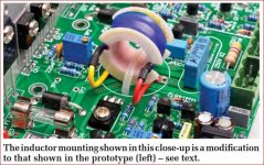
For the SC200, why did SC change the O/P inductor orientation from vertical to horizontal? It also changed on the ULD as I recall.
Looking at the Right-Hand Rule and Cherry's paper on mutual induction distortion, I don't see how a B-field parallel to the PCB (plane) is better than perpendicular.
Looking at the Right-Hand Rule and Cherry's paper on mutual induction distortion, I don't see how a B-field parallel to the PCB (plane) is better than perpendicular.
Attachments
Transformer voltage rating
Yes, you are right about the voltage rating. Measured an open circuit output voltage of 27.5 VDC on a toroid transformer rated at 25 VDC. So the regulation is going to be close to 10% for that particular example.
It may be that the initial development was done with the higher rated 45-0-45 transformer and at a later time a switch was made to the lower voltage. I can't seem to find any errata in Silicon Chip mag.
I wonder how much better this amp will sound when compared to an ETI480 or SC480? They were good robust amps.
BTW, Toroidal transformer voltage ratings are at full rated power, so regulation is irrelevant but in any case, 45VAC windings are going to give a lot more than 57VDC unregulated. It's just wrong or was intended for a higher supply as perhaps for just 8R loads, since the 2 pairs of lightweight output transistors will have a hard time up there.
Yes, you are right about the voltage rating. Measured an open circuit output voltage of 27.5 VDC on a toroid transformer rated at 25 VDC. So the regulation is going to be close to 10% for that particular example.
It may be that the initial development was done with the higher rated 45-0-45 transformer and at a later time a switch was made to the lower voltage. I can't seem to find any errata in Silicon Chip mag.
I wonder how much better this amp will sound when compared to an ETI480 or SC480? They were good robust amps.
The AES paper was rewitten as an ETI article.For the SC200, why did SC change the O/P inductor orientation from vertical to horizontal? It also changed on the ULD as I recall.
Looking at the Right-Hand Rule and Cherry's paper on mutual induction distortion, I don't see how a B-field parallel to the PCB (plane) is better than perpendicular.
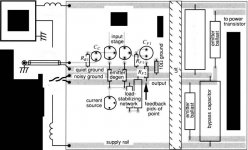
In that ETI article the fig3 PCB layout can be clearly seen.
It was posted here a few years back, but I don't know what Thread.
Having re-read the Cherry paper I now realise where my current thinking on local supply rail decoupling started from.
Cherry's and other articles appear occasionally in the DIY magazines and much can be learned from them.
Last edited:
I have found the same diagram in another Cherry article:
page 18 of "ironing out Distortion".
It was a Wireless World (Jan 1995) extension to D.Self article.
The .pdf is a 2.5MB file and exceeds the Forum's limit.
Is there a way to extract a part of this big .pdf ?
page 18 of "ironing out Distortion".
It was a Wireless World (Jan 1995) extension to D.Self article.
The .pdf is a 2.5MB file and exceeds the Forum's limit.
Is there a way to extract a part of this big .pdf ?
I wonder how much better this amp will sound when compared to an ETI480 or SC480? They were good robust amps.
Having built the Elektor Q-Watt Power Amp.......😎
Let's get some comments in from constructors of this project....😉
Last edited:
Post with illegal download link to material under copyright have been removed.
This serious infringement will be discussed in due course by the Moderation Team.
This serious infringement will be discussed in due course by the Moderation Team.
EPE here – I hope users won't mind if I drop in to say that a number of queries have come our way regarding the availability of the SC200 mains transformer and we are in touch with our counterparts at Silicon Chip about it. There’s no doubt that the SC200 is one of those challenging designs that use some pretty difficult esoteric components. One benefit EPE enjoys is that usually, any wrinkles or bugs have been ironed out by the time the design reaches our pages. Rest assured we will come back with latest news or suggestions direct from the designers themselves.
I personally handle the design and management of the EPE website and I’ll add more mods or comments when available. As some users here have pointed out, the best links are the monthly project pages on the EPE web site where I post any addendum or corrections for future reference.
We also run our legacy ‘Chat Zone’ in read-only mode. It is here where our legacy ‘Shop Talk’ feature contains component-buying news. Topics - :: EPE Chat Zone ?:: ?Radio Bygones Message Board ::
EPE also wishes to sincerely thank those forum users who are continuing to support us. Without newsstand sales or subscriptions there would be no home-spun hobby electronics magazine left in Britain. EPE particularly deplores copyright theft and piracy which are very damaging to small independent publishers like ourselves. Although we do take action including legal measures in the worst cases, it would cost us our entire turnover to police and nail down acts of piracy seen all around the web. So thank you again to those who encourage the legitimate and fair purchase of EPE.
EPEMag,
is there a time expiry for showing extracts from your magazines?
Like more than 20years old?
is there a time expiry for showing extracts from your magazines?
Like more than 20years old?
Old articles
We know that very old material from Everyday Electronics, Practical Electronics, EPE or (UK edition) ETI – (let's say 30 years+) pops up on the web which is unlikely to cause much of a problem provided it is not being monetised or re-sold. The principles of ‘fair use’ apply to using more recent material – ie small extracts are OK for discussions or reference purposes, as long as entire circuit diagrams, constructional projects or other copyrighted material aren’t republished without permission. If in doubt, we like to be asked and we never refuse permission for reasonable requests. Hope that helps!
Alan W / EPE
SC200 mains transformer
In case it helps, we have today published an update regarding the choice of mains transformer for the SC200 amplifier. From the designer:
The prototype used an Altronics MC5540 but it seems that part code has inexplicably been discontinued. They have also discontinued their full amplifier kits which included that transformer.
While I could probably find an equivalent device, I suspect it would be too expensive. The easier solution is to use two transformers: one 300VA 40-0-40 transformer and a 20-30VA 15-0-15 transformer like Jaycar MT2086 or Altronics M4915B. The mains primaries of the two transformers should be wired in parallel.
Arguably this is superior to a single transformer since the 300VA transformer is then tasked with only supplying the power amplifiers, so it will be able to supply slightly more peak current. It should also make chassis layout and wiring easier.
I don't understand why Jaycar and Altronics have both discontinued their 40-0-40 transformers since they surely would have sold a few, given that people continue to build our amplifier designs.
Nicholas Vinen
Editor
For future reference updates for EPE projects are also preserved in our legacy forum at :: EPE Chat Zone ?:: ?Radio Bygones Message Board ::: Shop Talk
Transformer for SC200
Thanks for this input. I think anyone intending to build this amplifier and who has questions about the amplifier transformer/power supply should wait for the March EPEMag or purchase the March 2017 Silicon chip magazine.
If you are only interested in powering the amplifier module you need to supply +/- 57VDC to the amplifier to get 135 watts average output. The supply voltage can be decreased down to +/- 42 VDC to give 75 watts average output. Some resistor changes are required in the SC200 for the lower power version.
Silicon Chip recommend a 300VA transformer (40-0-40 VAC) to power two amplifiers at 135 Watts output for typical domestic use.
The Silicon Chip amp PCBs look ok.
EPE here – I hope users won't mind if I drop in to say that a number of queries have come our way regarding the availability of the SC200 mains transformer and we are in touch with our counterparts at Silicon Chip about it. There’s no doubt that the SC200 is one of those challenging designs that use some pretty difficult esoteric components.
Thanks for this input. I think anyone intending to build this amplifier and who has questions about the amplifier transformer/power supply should wait for the March EPEMag or purchase the March 2017 Silicon chip magazine.
If you are only interested in powering the amplifier module you need to supply +/- 57VDC to the amplifier to get 135 watts average output. The supply voltage can be decreased down to +/- 42 VDC to give 75 watts average output. Some resistor changes are required in the SC200 for the lower power version.
Silicon Chip recommend a 300VA transformer (40-0-40 VAC) to power two amplifiers at 135 Watts output for typical domestic use.
The Silicon Chip amp PCBs look ok.
- Home
- Amplifiers
- Solid State
- SC200 Amplifier Module