@abstract What exactly is it you find problematic with drivers using a shorting ring, and how do you deal with drivers not using a shorting ring,a re you thinking of those remedies talked extensively in @Joe Rasmussen thread such as current drive and notch filters, or something else, if so then what?
Last edited:

@Ultima Thule, yes, current drive, or just any method like using a resistor or inductor for a 'mixed' output impedance. Especially at high frequencies and for high sensitivity speakers where you might not want the amplifier to provide too much correction in response to voltage and current 'echoes' produced by microphonic effects in the speaker.
Iirc. that discussion covered a different angle using large passive components to flatten the speaker impedance, whereas what I had in mind is more related to using high output impedance to be able to 'ignore' stray inductance that's in series with the sound-producing part of the voice coil.
Shorting rings do reduce stray inductance a lot as can be seen from manufacturer supplied graphs, but a side effect is a parallel path for current to flow through, so "current control" kind-of stops working as designed and I'm just being extra careful in case it adds more distortion than it removes. Ultimately it all requires testing and experimentation to be able to come to solid conclusions.
Alpair 5 & MAOP (afaict) : no copper
As far as i know they do. Look at the indictabce and the high frequency impedance. CHN-50 is a cheapy, it might well not (depends on whether there are a ton of Alpair 5 polepieces sitting unused. Looks like that may well be the case.
CHN-50 Le 1kHz = 0.06 mH
MAOP 10.2 Le 10kHz = 0.1391 mH
MAOP 5 Le 1kHz = 0.0681 mH
Alpair 5.3 Le 10kHz = 0.0399 mH
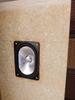
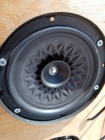
I have some baskets downstairs without cones for some Alpairs, i could take pictures.
dave
Composing metal foil with paper or plastic cones brings stiffness without adding resonances. It can put even resonances down.
But also heavily structuring the cone has stiffness benefits.
Some posts from me on the topic
https://www.diyaudio.com/community/threads/speaker-mods-on-an-el-cheapo-speaker.396970/post-7301755
https://www.diyaudio.com/community/...cone-problem-any-solution.393669/post-7213778
But also heavily structuring the cone has stiffness benefits.
Some posts from me on the topic
https://www.diyaudio.com/community/threads/speaker-mods-on-an-el-cheapo-speaker.396970/post-7301755
https://www.diyaudio.com/community/...cone-problem-any-solution.393669/post-7213778
Attachments
I must admit it's hard to tell just from the graphs. ~20 ohm @ 20kHz (for 8 ohm nominal) seems like a good low value, but is it 'magically low'?As far as i know they do. Look at the indictabce and the high frequency impedance. CHN-50 is a cheapy, it might well not (depends on whether there are a ton of Alpair 5 polepieces sitting unused. Looks like that may well be the case.
CHN-50 Le 1kHz = 0.06 mH
View attachment 1176739
MAOP 10.2 Le 10kHz = 0.1391 mH
View attachment 1176741
MAOP 5 Le 1kHz = 0.0681 mH
View attachment 1176742
Alpair 5.3 Le 10kHz = 0.0399 mH
View attachment 1176743
I have some baskets downstairs without cones for some Alpairs, i could take pictures.
dave
I checked a couple of datasheets and maybe they're a bit coy -- like for the chn-50 they mention "careful motor design" as the reason for the modest impedance rise. And for the Alpair 5 they make no mention, so it could be that they don't advertise the feature, or they use a shorter voice coil with less over-hang. Pics would solve the mystery.
but is it 'magically low'?
Not really, but it isn’t 100Ω.
My primamry source of info is long talks with the designer.
dave
Can you provide more info on passive XO components reducing distortion? I have yet to design a speaker or XO but am keen to learn from other's experience.Fully active XO? A nice idea for multi-amping and reducing some sources of IMD, but some passive components can also reduce distortion.
I never said it didn't cause other problems. I would still recommend multi-amping, using active filters especially for bass, and avoiding solid core inductors and some types of capacitors (bidirectional electrolytics and mylar/polyester).
But there are some things that active filters won't do. Active filters won't stop stray inductance at opposite ends of the voice coil from modulating the current passing through the middle part of the VC. Passive components like a resistor or inductor in series do help with that, because a voltage amplifier with a large impedance in series becomes a current amplifier. To achieve something similar with an active XO system and no passive filter components at all, you would have to starting experimenting with the amplifier itself.
Probably the easiest way to dip your toes into exploring the different sound, would be to start with an over-powered class-D amplifier and put a few ohms resistance (say, 10-22) in series between it and the speaker. Or a 1mH inductor. Then fine-tune it with DSP or an active filter to get the total filter slope that you want, and compare the resulting sound against the exact same filter slopes achieved using only DSP.
So if you look at the dotted part of the curve...

...that won't be perfectly stable. With low frequencies moving the VC around, that is likely to bounce up and down a little, causing amplitude modulation of the mid-range, especially 1kHz and up.
The (not so) 'ideal' fix for that would be a near-perfect current source with 1k ohm+ in series, so that +/- 1 or 2 ohms variation will have virtually no effect on the total current, but that's impractical, and could cause other problems like thermal runaway if the voice coil starts to get hot.
What they say seems pretty straight forward.
What should they say?
Something like=
" It is aluminum with some white stuff on it.
with a obnoxious dip at 50Hz , your gonna love it !! "
 Yeah.
Yeah.We put extra glue on our drivers.
I like extra glue and resistance to combustibility, but maybe I'm just weird lol
I actually love the way SB makes their drivers.
I like their 5" drivers.
Terminals and vents are nice on 8" drivers.
A lot of glue. Sloppy glue joints even on ScanSpeak drivers.
Leads are rarely glued perfectly on other drivers, unless they are glued sideways, if you know what I mean.
Thick cast baskets.
Yeah, "paper" is confusing. You can only recycle it 7 times lol
- Home
- Member Areas
- The Lounge
- SB Acoustics has some interesting marketing tactics, I can't tell if they're geniuses or morons