The back of my Sonatellos' cabinets were 5-6 inches from wall. They sat on the fireplace hearth, which is level with the floor where the fireplace front is in a corner at 45 degrees (I will dig up a photo to show you this arrangement but it won't be the Sonatellos, instead another pair of speakers similarly arranged).Hi Paul
Thanks again for all of your help.
I was looking up the Jantzen 4.0 mh coil and although they call it an Iron Core they say its actually a material called Permite and according to them is ideal for midrange and bass applications so I think it will be ok.
I have found one that is even closer at 0.215 ohms.
Withe regard to the placement of the bass unit I have a programme that shows the different room gains depending on how close the bass driver is to the floor, side wall and back wall which I can play with.
As a matter of interest how far from the side and back walls was the speaker designed to work best.
When I say back wall what distance from the back of the cabinet to the wall.
I am still intending to build it as a bass reflex with possibly a bottom port so I will get further gain there.
Thanks again
Colin

Hi Paul,The back of my Sonatellos' cabinets were 5-6 inches from wall. They sat on the fireplace hearth, which is level with the floor where the fireplace front is in a corner at 45 degrees (I will dig up a photo to show you this arrangement but it won't be the Sonatellos, instead another pair of speakers similarly arranged).
View attachment 1078494
Thanks again so close to all walls then.
One minor point, ìs the midrange 4 or 8 ohms.
On your crossover it is shown as 8 ohms but the person who built it on this site shows a data sheet for the 4 ohm version.
Colin
The midrange SB15NRX30-8 is what I used and is specified by SB as an 8-ohm driver, hence the "-8" at the end of its model number.Hi Paul,
Thanks again so close to all walls then.
One minor point, ìs the midrange 4 or 8 ohms.
On your crossover it is shown as 8 ohms but the person who built it on this site shows a data sheet for the 4 ohm version.
Colin
Paul
Hi Paul
Just one more question.
What sort of listening distance did you have.
I will be approx 2 metres away and wondered if the big gap between bass and mid will be a problem .
Thanks
Colin
Just one more question.
What sort of listening distance did you have.
I will be approx 2 metres away and wondered if the big gap between bass and mid will be a problem .
Thanks
Colin
Sorry to throw another option at you but just came across this -
Here is Scott Hinson's three way large stand mount using a 23NRX-8, 12NRX-8 and 26STCN. All info inthe link to make the speaker.
https://drive.google.com/file/d/1dW...erM9qwIlTLUDNZIoqRneTkBDQcT_c6ElQ8fNxwyjKiBhE
Here is Scott Hinson's three way large stand mount using a 23NRX-8, 12NRX-8 and 26STCN. All info inthe link to make the speaker.
https://drive.google.com/file/d/1dW...erM9qwIlTLUDNZIoqRneTkBDQcT_c6ElQ8fNxwyjKiBhE
Have seen that one but seems a bit bass heavy also all the drivers seem to be wired the same I thought that at least one should be reversed.Sorry to throw another option at you but just came across this -
Here is Scott Hinson's three way large stand mount using a 23NRX-8, 12NRX-8 and 26STCN. All info inthe link to make the speaker.
https://drive.google.com/file/d/1dW...erM9qwIlTLUDNZIoqRneTkBDQcT_c6ElQ8fNxwyjKiBhE
My ears are about 10 feet (>2 meters) from the baffles. Based on that distance and the distance between the cabinets (about 5.5 feet CTC), an angle of 15 degrees is created horizontally. A fellow DIYer and friend, Dan Neubecker, designed the crossover for me and he's an excellent designer; he optimized the design for my physical setup with the speakers firing straight ahead. If the speakers are separated further apart, simply toe them in appropriately. There was no audible disconnect between the mids and bass.Hi Paul
Just one more question.
What sort of listening distance did you have.
I will be approx 2 metres away and wondered if the big gap between bass and mid will be a problem .
Thanks
Colin
Paul
Whether or not polarity should be reversed depends on the crossover topology. As far as i can tell this is third order so no need. Seems like it fits what you want exactly. You can always make it sealed to shift the bass alignment, but honestly i think that Scott Hinson's looks like a nice and cheap 3-way build.

I just read the Scott Hinson design paper. I like that speaker. Easy to construct, very well documented, and the measured performance looks very good.
j.
It may be an artifact of the way he measured low frequency performance to input to the simulation, but even if it is real, it is the kind of modest bass emphasis that most people find appealing. Most people prefer the in-room listening position response to drop by about 1 dB per octave from 100 Hz to 10 kHz, which is a 6 to 8 dB drop.Have seen that one but seems a bit bass heavy
Not necessarily. The specific details of the drivers frequency response and phase response, plus the different time delays of the drivers will determine whether or not a driver is used in reverse polarity.also all the drivers seem to be wired the same I thought that at least one should be reversed
j.
Scott is a very accomplished designer, and this design looks to have had a great deal of time and effort put into measuring, modeling, and iterating. It's rare to see a design so thoroughly thought through and documented. Did you see a glaring issue in the measurements provided that suggested some of the drives should have their phase reversed?Have seen that one but seems a bit bass heavy also all the drivers seem to be wired the same I thought that at least one should be reversed.
The Scott Hinson does look interesting but it is a bit wider than I want to make it, if I made it say 10.5 inches wide would that be a problem with the xover and also it will be very close to the back wall.
I see the crossover is around 400hz from Woofer to Mid on the Scott Hinson design so I woild think that changing the cabinet width from 304mm to say 260mm is not a big deal.
With regard to the crossover (remember I am a novice) I assume that where the inductors are the Resistor next to it is the DCR of the inductor.
If so am I right that L22 is 0.2 mh and the resistance is 4.5 ohms and L9 is
1.0 mh and the DCR is 4.0 ohms
With regard to the crossover (remember I am a novice) I assume that where the inductors are the Resistor next to it is the DCR of the inductor.
If so am I right that L22 is 0.2 mh and the resistance is 4.5 ohms and L9 is
1.0 mh and the DCR is 4.0 ohms
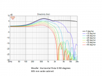
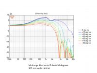
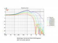
I slapped together a quick simulation of baffle diffraction to see what the differences would be between the original 305 mm wide cabinet and a 267mm wide cabinet. I simulated the woofer and the midrange in their proper vertical orientation, the only thing that changes is the width.
It is not a big difference, but there is some difference. The BSC features of the original crossover will probably be acceptable. I suspect that a 267mm wide version of this speaker would sound similar to the original... subtly different, but similar.
Be aware that the whole cabinet will have to be redesigned to maintain the same internal volume as the original, and the midrange sub-enclosure should not change shape.
j.
Attachments

Thanks HiFi Jim.
With regard to the crossover (remember I am a novice) I assume that where the inductors are the resistor next to it is the DCR of the inductor. Or is it in addition to the DCR of the inductor.
Is L22 0.2 mh and the DCR 4.5 ohms and is L9
1.0 mh and the DCR 4.0 ohms.
I am confused.
With regard to the crossover (remember I am a novice) I assume that where the inductors are the resistor next to it is the DCR of the inductor. Or is it in addition to the DCR of the inductor.
Is L22 0.2 mh and the DCR 4.5 ohms and is L9
1.0 mh and the DCR 4.0 ohms.
I am confused.
I imagine that is the total resistance that should be in series with that inductor. In some of the cases the resistance seems to correspond to what you would expect for an inductor that size, but 4R is definitely too much for a 1mH inductor, and so is 4.5 for 0.2 mH. In those cases you should add resistance to reach the required. Only my 5c.
Hi silasmellorI imagine that is the total resistance that should be in series with that inductor. In some of the cases the resistance seems to correspond to what you would expect for an inductor that size, but 4R is definitely too much for a 1mH inductor, and so is 4.5 for 0.2 mH. In those cases you should add resistance to reach the required. Only my 5c.
You may well be correct as when I look at the photos of the crossovers I can see 4 resistors and that would be in line with your thoughts.
Hope we are right fo if I go ahead and I am wrong there will be problems.
One more question on the SBx3 crossover if I want to increase HF output which resistor would I decrease.
I am old and a bit deaf.
I am old and a bit deaf.
Regarding post#34, I agree with silasmellor. When you select your inductors, you need to match the series resistance with whatever value is in the schematic. This would be a combination of the inductor's DCR and other resistors added in series.
The resistors in series with the tweeter control the level of the tweeter... However, I would build the system as-is first. After evaluating it for a while you can decide if you want to modify it. You may decide that the tweeter level is best handled with a bit of EQ rather than a permanent modification to the speaker.One more question on the SBx3 crossover if I want to increase HF output which resistor would I decrease.
- Home
- Loudspeakers
- Multi-Way
- SB 3 way