but the signal manages to reach the base of Q17-Q18, as you can see in post #21, if I measure the voltage drop across R43 and R44 I get a voltage, as well as across the resistors R45 and R46;I can't fathom how DC voltages can drop in reasonable fashion through the cascade of transistors (eg. Q13,Q15,Q17), and fail to simultaneously transfer the sine wave drive through each b-e junction.
This is what I measured at the bases of Q13, Q15, Q17 and at the emitter of Q17, similarly for Q14, Q16 and Q18I suggest using your scope to step through each stage, with scope set for DC coupling. Drive amp input with sine wave to deliver about 0.2V pk-pk at base of Q13. Your scope should show dropping DC voltage at each junction (base, then emitter) as you step in order from Q13, Q15, Q17 followed by emitter, then base of Q18, Q16, Q14. The sine wave should follow supper-imposed on the DC bias, with only minor drops in AC amplitu
Q14 Vb
Q16 Vb
Q18 Vb
Q18 Ve
Q13 Vb
Q15 Vb
Q17 Vb
Q17 Ve
Last edited:
yes, I measured 0.5 OhmRiffing on this theme, measuring from the emitter of Q17 at the package body to board edge terminal 13 should show a few tenths ohm, i.e. R43 + winding resistance of transformer L1; similar for emitter of Q18.
These waveforms all look good to me, and are reasonably consistent with the data you posted in #13. I assume if you scoped emitters of Q19 and Q20, you'd find similar waveforms.
I see you've confirmed reasonable resistance, on both Q17 and Q18? Have you traced the sine wave from the main output toward the speaker binding posts? Where does the signal fail on the path toward the dummy load? Does output change amplitude if you remove the load and test open circuit? The resistance seems reasonable, but be suspicious of the transformer. Let us know what you observe.
I see you've confirmed reasonable resistance, on both Q17 and Q18? Have you traced the sine wave from the main output toward the speaker binding posts? Where does the signal fail on the path toward the dummy load? Does output change amplitude if you remove the load and test open circuit? The resistance seems reasonable, but be suspicious of the transformer. Let us know what you observe.
Last edited:
My approach to repairing a defunct Sansui amp 2years ago was to print out the parts list for the power amplifier section and to measure resistor values and use a green highlighter pen to mark the various parts which were good and and a red one to mark those that were defunct. In this way you have an image which is portable. There were some defunct carbon film resistors as I remember which I replaced. You also have the voltage points to check against your actual measurements which you could highlight in green if good and red if otherwise - in that case you could write any incorrect voltage on the print out master image.
yes i did, the waves are similarThese waveforms all look good to me, and are reasonably consistent with the data you posted in #13. I assume if you scoped emitters of Q19 and Q20, you'd find similar waveforms.
yes I have a reduction in voltage when I remove the loadDoes output change amplitude if you remove the load and test open circuit?
I’m losing sight of the original problem. I’m probably being dense, but would you guide me along the path to the problem you’re encountering?
Thanks.
Thanks.
To recap......
the problem I found is the low output power (about 25W); I think that only the distortion correctors are working because, what I measure at the output terminals, is precisely the power of those transistors;
as you have seen and said, the signal has its shape without distortions or strange shapes, the voltages are consistent with those from SM;
I think we are missing something terribly banal.....
TRAFO:
in post #24 you mentioned a possible malfunction of the transformer; I think that if the output voltages match I shouldn't worry too much, among other things I also used the two primary windings of 220Vac and 240Vac, so the primaries should be ok; I will also try to use 100Vac and 120Vac, you never know....
if the transformer were to break I really don't know where to get one.
I really appreciate what you are doing and the advice you are giving me, I hope to solve it
I think we are missing something terribly banal.....
Agreed!
To recap......
the problem I found is the low output power (about 25W); I think that only the distortion correctors are working because, what I measure at the output terminals, is precisely the power of those transistors;
as you have seen and said, the signal has its shape without distortions or strange shapes, the voltages are consistent with those from SM;
Would you confirm some measurements for me?
I assume you are measuring power at the speaker terminals into an 8 Ohm resistor, a sine wave test signal driven to threshold of clipping? 25W would imply 12.27VRMS= 20V peak re ground. Is this about what you observe? At the same drive level, would you report the observed voltages at the main amp output (junction of R43, R44) and at the emitters of the distortion correctors, i.e. Q19 and Q20 ? Peak voltage re ground is convenient. I'm assuming the waveforms are clean sine waves. Would you also advise observed supply rail voltages in the same drive conditions?
Is your amp an "Export Only" model, as they have different resistor values at R43 through R46? Note that R45 and R46 plus R47+R48 severely limit the available power delivered to the speaker. This path is intended to cancel distortions generated within the main amplifier--- they are probably ~40dB below the main output.
Finally, would you describe the L1 transformers? Can you tell if they have a core? Can you measure the resistance of each winding? I think you can measure without removing from the board. Approximate values are sufficient.
Thanks!
Last edited:
the model in my possession is Export because I have 0.33 resistors and 1169/2773 transistorsIs your amp an "Export Only" model, as they have different resistor values at R43 through R46? Note that R45 and R46 plus R47+R48 severely limit the available power delivered to the speaker. This path is intended to cancel distortions generated within the main amplifier--- they are probably ~40dB below the main output.

I’m losing sight of the original problem. I’m probably being dense, but would you guide me along the path to the problem you’re encountering?
Thanks.
The purpose of the output stage is to increase current with rising input voltage to the amplifier.To recap......
the problem I found is the low output power (about 25W); I think that only the distortion correctors are working because, what I measure at the output terminals, is precisely the power of those transistors;
as you have seen and said, the signal has its shape without distortions or strange shapes, the voltages are consistent with those from SM;
I think we are missing something terribly banal.....
TRAFO:
in post #24 you mentioned a possible malfunction of the transformer; I think that if the output voltages match I shouldn't worry too much, among other things I also used the two primary windings of 220Vac and 240Vac, so the primaries should be ok; I will also try to use 100Vac and 120Vac, you never know....
if the transformer were to break I really don't know where to get one.
I really appreciate what you are doing and the advice you are giving me, I hope to solve it
f there is a problem in the voltage amplifier and the wave-forms all good apart from being low then it should be mentioned that the voltage gain is dependent on the negative feedback path divider - the feedback resistor connecting to the inverting input terminal and the values of components in the arm of the divider which connects to ground. Usually this consists of a resistor and series capacitor. If there is a disconnection in this later path the amplification of the amplifier will be unity. That is one - The voltage output above one is the value of the feedback resistor over that of that in the divider arm that connects through the series capacitor to ground. e.g if the former is say 22k Ohms and the latter is 1k Ohm the answer is effectively 22 times. Of course the power supply rails have to be adequate for the expected power output reliant on the transformer rectified voltage. You can check what the circuit diagram shows and what you have can measure as available. If you can only get 25 watts in tests your rectified power supply rails will be around 25 volts which is dubious.
Last edited:
STOP, EVERYONE!!!
I found the problem, and I'm ashamed of it....
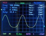
in all the devices I had to do the power handling tests I always injected a signal of 100mV@1kHz, even with this amplifier I proceeded in the same way obtaining the results that you all know (that is, about 25W, ±12Vrms@8Ohm);
I carry out the checks recommended by BSST and I find that the transformer has no obvious problems, so while I read and reread the SM, in the technical specifications, under "Input sensitivity and impedance" I read that for the AUX, TUNER and TAPE inputs the sensitivity is 250mV!!!
well, doing my measurements with this input voltage at a frequency of 1kHz I now see the ''95W'' at the output terminals!!!
Surely for some of you it is a given that the test must be done taking this data into consideration;
this is what I see at the output of the terminals with the knob at full scale!

I found the problem, and I'm ashamed of it....
in all the devices I had to do the power handling tests I always injected a signal of 100mV@1kHz, even with this amplifier I proceeded in the same way obtaining the results that you all know (that is, about 25W, ±12Vrms@8Ohm);
I carry out the checks recommended by BSST and I find that the transformer has no obvious problems, so while I read and reread the SM, in the technical specifications, under "Input sensitivity and impedance" I read that for the AUX, TUNER and TAPE inputs the sensitivity is 250mV!!!
well, doing my measurements with this input voltage at a frequency of 1kHz I now see the ''95W'' at the output terminals!!!
Surely for some of you it is a given that the test must be done taking this data into consideration;
this is what I see at the output of the terminals with the knob at full scale!
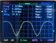
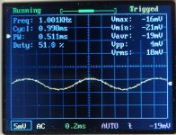
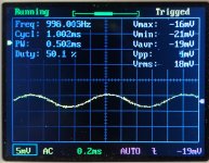
Your scope claims 29.2Vrms. That corresponds to 106.6W !
If the displayed signal is shy of clipping, full power may be even higher.
Looks good to me.
If the displayed signal is shy of clipping, full power may be even higher.
Looks good to me.
Your scope claims 29.2Vrms. That corresponds to 106.6W !
If the displayed signal is shy of clipping, full power may be even higher.
Looks good to me.
yes, but I brought the input signal to 250mV and turned the volume knob expecting the wave to clip but I reached the bottom of the scale....... I don't know how many times this condition will occur with my playback devices;
also consider that the oscilloscope is a Chinese thing and I need it to give an idea of the signal that comes out of a device, for me, it's more than fine, so even if those 29.20V are 28 or 27 it doesn't change much for me, it's fine and I'm very happy that this amplifier starts playing again after 7 years.
I thank all of you for the advice given, with this opportunity I have learned more about this amplifier and naturally I will make a precious baggage of everything that has been told to me;
in the coming days I will go to listen and I will give you my impressions
Thanks again!
Here I am, finally with my Sansui working, and I will never stop thanking you.
After listening to my amplifier for a few days I can draw my conclusions, certainly positive but with a small note;
the power is there, and how..... now I can push my self-built speakers (Coral/Peerless RS108 project) as they should be;
I must say that I have never heard them sing so with such transparency, clarity, detail, in short a full and clear sound, a bit due to the characteristics of the speakers but above all due to the capacity of this amplifier, especially at high volumes;
I only have a small note to point out, I hear a slight preponderance on the medium frequencies, which in some scenarios is also slightly annoying;
of course I also tried with other speakers (ESB 75LD), and although with less evidence, it always manages to have a bit of emphasis on the medium frequency;
going back to the amplifier, as written in the first post I replaced some drivers and the distortion correctors;
the originals are Toshiba 2SA968 - 2SC2238, while as a replacement I found some ISC (Inchange Semiconductor Company Limited), thinking that they had the same characteristics;
technically they may have the same characteristics but at a sound level I think there are some subtle differences;
I searched online for some discussions on the subject and they confirmed what I said above, that is a slight predominance to accentuate the medium frequencies;
what do you say, should I look for some Toshiba?
do any of you use this brand and have noticed something like this?
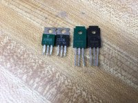
Toshiba is no longer making those, so be careful what you get and where. They were the among the best drivers ever made. Fakes are everywhere, and ISC in general isn’t as good as original types. There are documented examples of outright failures in Sanken clones. KEC may be making them now and I’d give them a shot before trying anything of new manufacture. If you find NOS, make sure they look like THESE, including the green cased PNPs. The ones to the right are the type that replaced them. Same thing in a full molded package. Also out of production, but there is more NOS stock out there in these types.
DO NOT buy Toshiba labeled product in the lead-free finish! They stopped making these before they made the switch.
And no, the C4793/A1837 pair is not as rugged.
DO NOT buy Toshiba labeled product in the lead-free finish! They stopped making these before they made the switch.
And no, the C4793/A1837 pair is not as rugged.
Attachments
I read on some forum that Toshiba has changed the logo and you can still find something with the new logo, but I don't know if the quality is the same or they are fake copies;
I found some pairs in an online store in my country, where I bought Sanken (2SA1295/2SC3264) for this Sansui and they work great;
it's a store where several repair technicians buy, maybe the ones he sells are NOS?
I found some pairs in an online store in my country, where I bought Sanken (2SA1295/2SC3264) for this Sansui and they work great;
it's a store where several repair technicians buy, maybe the ones he sells are NOS?
Attachments
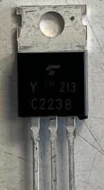
That’s the new logo, but that is the lead-free finish I was telling you about. FAKE. Toshiba was still using the lead/tin dipped solder plated legs when they quit making those types. In the early 2000’s. That package was made recently, so it can’t be a real Toshiba.
If those “Toshiba C2238’s” don’t blow up, they may be MJE15032 clones. Which would hold up fine - they are a much BIGGER part. Overall amplifier performance may or may not be as good. Those MJEs (from ON) are a solution for replacing C2238 if you’re not worried about ultimate performance and just need something rugged. Like when rebuilding a QSC USA1310.
If those “Toshiba C2238’s” don’t blow up, they may be MJE15032 clones. Which would hold up fine - they are a much BIGGER part. Overall amplifier performance may or may not be as good. Those MJEs (from ON) are a solution for replacing C2238 if you’re not worried about ultimate performance and just need something rugged. Like when rebuilding a QSC USA1310.
Last edited:
- Home
- Amplifiers
- Solid State
- Sansui AU-D9 – Power transistors not amplifying after restoration