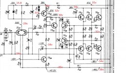
I started working on a nice Sansui AU 5900. It powers up ok but the relay doesn't engage so I tested for dc offset and got -21v on one channel and an ok but not great 150mV on the other. So far I have replaced those famous vd1212 diodes and R31 and R41 on the dead channel. One of those resistors read 1.3k instead of 220 as it should be. I fired it up again and now I got -33v of dc which seems logical as R31 is on the negative power supply rail for the voltage amplification circuit.
I tested all the transistors one by one disconnected from the board but they all test ok. I've done a quick check of the resistors but they measure the same as on the good channel.
According to the amount of dust and dead insects that were stuck on the circuit I suppose this amp has never been worked on so all original.
Ideas on where to look next would be welcome 🙂
If you register at HiFiEngine.com you can get a copy of the schematics.
Then it is a fairly straightforward process of reading the voltages at various points from both channels.
Comparing the channels should reveal where your problem lies.
Then it is a fairly straightforward process of reading the voltages at various points from both channels.
Comparing the channels should reveal where your problem lies.
The service manual shows the correct voltages around the circuit on the bottom of the two power amplifier schematics. Are you sure you have a good 0V ?
Check the voltages around R31 and R32
Check the voltages around R31 and R32
My 0v is the chassis and the readings are correct on the good channel. I will take a copy of the the service manual, write my readings next to the ones that I should have and post it here.
Could you please post all the voltages around every transistor, we might be able to see what is switched ON or OFF that shouldn't be.
TR14,18,22 seem to be hard ON which they shouldn't be.
TR14,18,22 seem to be hard ON which they shouldn't be.
Last edited:
--Expect a handfull of capacitors to be replaced
--Expect a number of resistors to be open or drifted ( focus on 220R 4 of them )
--Expect problems on the secondary PSU
--Expect 2SA798 to be faulty ( notorious for that )
Other than the above these amplifiers never fail ....
Kindest regards
Sakis
--Expect a number of resistors to be open or drifted ( focus on 220R 4 of them )
--Expect problems on the secondary PSU
--Expect 2SA798 to be faulty ( notorious for that )
Other than the above these amplifiers never fail ....
Kindest regards
Sakis
I will post another one with the voltages on all the transistors.
Hi Sakis!
I have replaced the 4 220R resistors.
I will replace all the electrolytic caps anyway, are you also referring to ceramic caps ?
I tested the 2SA798 of the faulty channel and the reading were ok BC and BE both ways were about 0.65.
By the secondary PSU do you mean the one on top of the amp, with the selectors ?
The bottom of R02, R06 & R14 should be 0V I think.
This looks like signal ground and its at -34V
This looks like signal ground and its at -34V
Last edited:
I juste flipped over the amp to do some more measurements and I turned on the amp, the relay engaged and I now have 16 mv dc on one and 14 mv dc on the other channel. I would guess a bad contact somewhere but all the solder joints seem ok.
Plugs and sockets rarely cause amp failure. They might stop the amp from working by disconnecting power or signal.
I re-soldered the whole board and this seems to have done the trick although I'm not 100% sure. But I still have a DC offset on one channel that is fluctuating between +1.8v and -2.9v. Also the voltages on the bases and emitters of TR11,13,15 and 17 are very unstable as well.
I changed the electrolytic caps and that didn't change anything so I started de-soldering (1 leg only) all the resistors for testing and they are all within 5% of spec. Now when I was done soldering them all back in the dc stabilised at -76mV so I guess there was another broken joint somewhere. I will replace the two input transistors anyway and maybe I will get even closer to 0v offset. Anyway, I would say, result, thanks for all the help.
- Status
- Not open for further replies.
- Home
- Amplifiers
- Solid State
- Sansui AU 5900 dead channel
