Ian it could be the language thing as I'm in Sweden but what you tell me to measure is what I think I already did a measure on at post 1.
The wires coming out from the PS are 2 brown and 1 blue that go to the fuse holder ? Or can you tell me more detailed where you mean I should mesure as you would talk to a baby

Sextafondo, ever single cap on all boards have been replaced. I think it was approx 40+ of them.
Thanks again.
The wires coming out from the PS are 2 brown and 1 blue that go to the fuse holder ? Or can you tell me more detailed where you mean I should mesure as you would talk to a baby
Sextafondo, ever single cap on all boards have been replaced. I think it was approx 40+ of them.
Thanks again.
Sextafondo, ever single cap on all boards have been replaced. I think it was approx 40+ of them.
Thanks again.
Wow, those are a few caps 😀
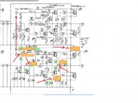
Check the image below out, and try to measure those test points in the amplifier circuit board. You have to take measurements on both R and L channels.
I suggest you first locate each test point with the amp OFF; then turn it on and measure. Be careful with the multimeter leads as they can slip, make a short and burn the stage. If you can, attach the multimeter leads with clips to the test point under measurement and then turn the amp ON.
Also, locate proper ground for the black multimeter lead, which is at the PS and corresponds to the transformer center tap wire.
Attachments

1000 thanks Sextaafondo. This will really help me. So much easier to understand by show instead of tell. As soon my 2 year daughter gone to sleep I will go out measure these points. Thanks again. I owe u one 🙂
Yes Evilution, I did make these suggestions before, in post #11. I had to assume you didn't understand as you didn't respond.
Are you using "Google Translate", because I was careful to use simple, formal expressions? Perhaps I should use US slang, jargon or street-talk. Google may read that better.
What I said is precisely what sextaafondo has now highlighted in colour for you. The arrows pointing to the voltages to be measured, on the schematic diagram of the lower amplifier, were there all the time.
Pablo. Thanks, that is the attitude I like. If you have car, guitar or computer problems, I can help... Here I need help =D
Ian. Yes you said what he showed to me. When you never done it before show is way more easier than tell. So I'm thankful to you too but this is new to me and I couldn't turn out what you said into "how to actually do it". Sorry for that but we all need to learn and we cannot be superior on everything in life...
Anyway, going to measure soon but I had time to re-solder the whole amp board just "in case". Now I have a loud "hmmmmm" sound on the right channel which was totally dead before. The hmmm sound is not following the volume or balance and is in headphones+speakers.
Will be back soon with the measuring.
Thanks again.
Ok did some further inspection yesterday.
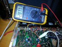
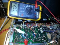
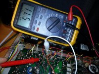
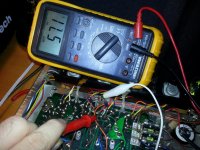
Pictures is included with my values. I have 55,7 where I should have 27V if I read it correct. Otherwise the values is correct.
What strikes me thou is the value on the right channel that is the dead one have a output on only 28 while the left have an output on
Pictures is included with my values. I have 55,7 where I should have 27V if I read it correct. Otherwise the values is correct.
What strikes me thou is the value on the right channel that is the dead one have a output on only 28 while the left have an output on
Attachments
Pablo. Thanks, that is the attitude I like. If you have car, guitar or computer problems, I can help... Here I need help =D
I take your word on this one 😀
Please, measure on the same test points in the good channel and write the numbers on the pic as you did with the bad channel.
Also measure DC voltage on the output connector for the speakers. Reading on this should be zero in the good ch, but could be we have some value on the bad one.
There are so far a couple -main- possibilities about the issue. First one is that during the caps replacement and later resoldering a couple traces got accidentally jointed with solder. That is pretty easy to happen on some printed circuits, not sure on this one, but you should check out that all traces are separated from each other as they should.
In this respect you should have a printed picture of the image in the service manual and check the board against the picture, in some cases with the help of the multimeter in 200 ohm range mode to make sure there is no short circuit between traces.
The second possibility is, due to trace short or not, some transistor may have got damaged, in which case you should decide whether you want to continue repairing it or not. For me it is OK and I will continue assiting you until you solve the problem and have a running amplifier on both channels again.
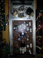
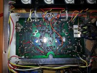
Take a look at the pic as I pointed out some possible conflicting areas. May be more of them.
You may wipe out all solder resin residue with a small brush (could be a toothbrush) and alcohol. Removing the resin will allow to see any possible short and then confirm with the multimeter. Hopefully you will find something of the sort as the amp was running fine before the re cap.
Let me know 🙂
Attachments
Yes, the pics help us understand more of what has happened before. Those 5A fuses replacing 2A fuses might seem a good idea but they cannot protect anything.
It is too late to follow this advice now, though all conventional amplifiers should be powered up after major repairs, with a bulb tester.
This is strongly advised in almost every fixit thread here for good reasons. Please, build one for yourself with approved, insulated mains parts before trying to power up the amplifier again.
http://www.diyaudio.com/forums/equipment-tools/252386-bulb-limiter-testing.html#post3844592
I agree with clean-up and close inspection of the solder joints made during recapping. Faulty components or wrong voltage ratings are unlikely so a
soldering fault or mistake in the polarity or lead arrangement of a cap. is still the logical conclusion. What has happened as as result may not be so simple or good to know.
Pablo, I'm a man of my word 😀
Pablo and Ian I'm insane thankful for all help and tips and I will go on with this amp until it works again. I'm never giving in hehe ...
Anyway. I cleaned it up and checked the solder joints and also did some new measure yesterday. Unfortunatly that didn't help. Was going to start measure more while I noticed the right side of the amp got INSANE HOT. Then a little smoke came up from the amp like tiny tiny and in between ... So I turned the amp off .. Let it cool off ... The turned around the amp and took my IR termomether ... Starting from 30 degrees on all 4 resistors .... After power it up without any volume. After approx 1-2 minutes ... Right channel (2 resistors) was over 55 degrees celcius ... Left channel was 35 degrees... So the resistors on the bad channel is over heating and it goes very very fast....
The HMMMMM sound is still on the right channel but now I carefully checked all joints and soldering... They are ok...
Not sure if you have any ideas about this with the resistors ? Will go on doing all measuring as soon I have the time but as the resistors will overheat it will be hard to do it ?
Ian that bulb tester will be built indeed!! Thanks for the advice.
If you have any hints on the resistors please let me know ... Still I'm confused whats causing them to heat so fast ...
Thanks again and cheers from Sweden! 🙂
Hi,
In thread 27 you point out that you have 54 volts instead 27 volts. To get that voltage TR812 must have 54 volts in the base. Normally you have 57/2 = close to 28 volt. Check the base of TR812. I can't read too good the number but I think it is TR812. It should have 28 volts at the base. Compare this TR812 with the same transistor with the good channel. Which resistor are getting hot?
In thread 27 you point out that you have 54 volts instead 27 volts. To get that voltage TR812 must have 54 volts in the base. Normally you have 57/2 = close to 28 volt. Check the base of TR812. I can't read too good the number but I think it is TR812. It should have 28 volts at the base. Compare this TR812 with the same transistor with the good channel. Which resistor are getting hot?
Pablo, I'm a man of my word 😀
Pablo and Ian I'm insane thankful for all help and tips and I will go on with this amp until it works again. I'm never giving in hehe ...
Anyway. I cleaned it up and checked the solder joints and also did some new measure yesterday. Unfortunatly that didn't help. Was going to start measure more while I noticed the right side of the amp got INSANE HOT. Then a little smoke came up from the amp like tiny tiny and in between ... So I turned the amp off .. Let it cool off ... The turned around the amp and took my IR termomether ... Starting from 30 degrees on all 4 resistors .... After power it up without any volume. After approx 1-2 minutes ... Right channel (2 resistors) was over 55 degrees celcius ... Left channel was 35 degrees... So the resistors on the bad channel is over heating and it goes very very fast....
The HMMMMM sound is still on the right channel but now I carefully checked all joints and soldering... They are ok...
Not sure if you have any ideas about this with the resistors ? Will go on doing all measuring as soon I have the time but as the resistors will overheat it will be hard to do it ?
Ian that bulb tester will be built indeed!! Thanks for the advice.
If you have any hints on the resistors please let me know ... Still I'm confused whats causing them to heat so fast ...
Thanks again and cheers from Sweden! 🙂
Evilution, sorry for the late response. There is the possibility at this point that a transistor (may be more than one to be honest) is burnt (shortcircuited).
Most likely ones are TR812 and TR808.
Also, please point out which are the resistors that are getting hot. We will go on based on this.
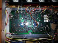
@Welcome The cardboard was the Swedish update just as the fuse holder =P I know it looks insane but I glued them to the old rings and will remove the cardboard soon. Just using them to "push the caps while glue drying".
@tauro0221 Yeah that is indeed strange. You mean each channel should have approx 27V or that each channel should have approx 54V ?
@Pablo no worries. I'm just thankful you replay, no rush =)
I think you are right. As I live in Sweden everything is much harder to get hold on and delivery time from US etc take time... I will replace all resistors, transistors and yeah all parts for the right channel (beside the capacitators) as they already been replaced and see how it turns out ... If it works perfect I order one more batch for the other side too ...
Or am I stupid if I go that way ? Not many components to replace anyway ... Feels like it will go faster this way than order part by part and wait for delivery =)
Thanks again guys!
Replacing everything is your last chance. I'd try to find the faulty components right now. It's also your opportunity to learn what failed and probably why it happened.
Again, which are the resistors getting hot? Knowing that'd help tracing the issue.
Again, which are the resistors getting hot? Knowing that'd help tracing the issue.
@Pablo that's indeed true. Maybe the "lazy" way to go.
Sorry forgot. The resistors that you can fry egg on is TR814 and TR812
I suppose they are for the right channel which also is the "dead channel".
Sorry forgot. The resistors that you can fry egg on is TR814 and TR812
I suppose they are for the right channel which also is the "dead channel".
TR812 and 814 are the output transistors for the right channel.
Please, remove them carefully from the circuit by unsoldering the wiring running to them (*); then turn the amp ON and, again with great care, measure all test point voltages and post them again.
(*) Take note of where each wire goes!. A pic might help later as well.
I'll explain how to measure the transistors integrity later.
As far as I read, there is a known reliability issue with all those transistors in the Sansui amp. Nothing that can't be solved pretty easily though.
European replacement options for Sansui's "flying saucers" transistors - AudioKarma.org Home Audio Stereo Discussion Forums
Last edited:
Those unusual parts with "in-house" numbers (8002-1, 9002-1) are the are driver and VAS transistors. The output transistors ( 2SC1030) can be replaced by a few standard types of TO3 transistors, as long as gain (Hfe and Ft) is high enough.As far as I read, there is a known reliability issue with all those transistors in the Sansui amp. Nothing that can't be solved pretty easily though.
European replacement options for Sansui's "flying saucers" transistors - AudioKarma.org Home Audio Stereo Discussion Forums
Do not simply apply power for testing or any reason without a current limiting device, regardless of whether damage has already been done. Please test the status first by using a bulb tester as advised before simply hitting it with full power or you will risk further damage.
It's possible for experienced technicians, who know the amplifiers well enough to operate without safety precautions but a first time DIY can't be expected to know what dangers are present and how amplifiers fail when mistakes are made.
If it hasn't already happened and you then blow those special transistors as well, you will have to replace virtually everything with only approximate equivalents and learn a lot of "how to" procedures to check for correct fitting and operation. You may get the amplifier to work again but how it will perform compared to original is just guessing.
Last edited:
In any case, and if I'd have to find replacements for any given transistors I'd replace them in both channels, killing any difference in performance beetween them.
- Status
- Not open for further replies.
- Home
- Amplifiers
- Solid State
- Sansui AU 555a One dead channel ? No power ?