Thanks again for all inputs guys! Would be lost without your help here...
Haven't been able to put any time on the amp last days but I will go berserk on it soon again 😀
Will do some more measuring first to see what could cause the fault and if it looks "ok" I will go on with the transistors.
Btw, anyone know where I can find those "cememnt blocks 2W 0.5ohm" ... Seems impossible to find even on ebay?! Think one of those are damaged....
Thanks againa and I will hit you back as soon I put some more time on it and tell you what's happening!!
You will find several suppliers of wire-wound resistors in Sweden. You don't strictly need square block types
and these are usually now only available in 5W. 2W is a minimum rating - anything up to 5W is OK.
You may realise 0.5 ohms (0R5) 10% covers a lot of other values like the standard value 0.47 ohms (0R47)
AC03000004707JAC00 - VISHAY DRALORIC - RESISTOR, 3W, 5%, 0R47 | Farnell Sverige
and these are usually now only available in 5W. 2W is a minimum rating - anything up to 5W is OK.
You may realise 0.5 ohms (0R5) 10% covers a lot of other values like the standard value 0.47 ohms (0R47)
AC03000004707JAC00 - VISHAY DRALORIC - RESISTOR, 3W, 5%, 0R47 | Farnell Sverige
Thanks Ian. I didn't know that. What was the reason of the "cement blocks" back in those days ? Then it will be way more easier to get hold on it. Thanks again for the great tip!
The blocks are rugged, industrial parts for use at high temperatures and extreme pulse duty.
'Nice if your amplifier runs at >60 C but for domestic audio, film resistors can be used even.
The issue is about flameproofing and that was a cheap, available form of wire resistor.
In Europe, ceramic coated, open cylindrical forms like this one are typical. Times change.
'Nice if your amplifier runs at >60 C but for domestic audio, film resistors can be used even.
The issue is about flameproofing and that was a cheap, available form of wire resistor.
In Europe, ceramic coated, open cylindrical forms like this one are typical. Times change.
Thanks for the info Ian. And thanks for the link Welcome!
Ok. Now I'm pretty sure I have a ghost in the amp ... Was going to measure it up tonight totally and when measuring C812 I got 52V on the multimeter than it said bang and the right channel fuse blow. Replaced the fuse and it blew again. So now I'm indeed even more lost ...
From recapping without "touching anything else" -> dead right channel -> humming right channel -> fuses blowing on right channel ... ?!
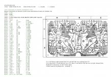
I have included a picture with all values of what I was able to measure before the fuses started to blow. Now I cannot even power up the amp....
Yes could be my lack of knowledge but all I did was putting multimeter on volt and put it with clips on + and - poles with great care.... C812 made it go down......
Anyone =) Thanks! <----- Swedish Elk =)
Ok. Now I'm pretty sure I have a ghost in the amp ... Was going to measure it up tonight totally and when measuring C812 I got 52V on the multimeter than it said bang and the right channel fuse blow. Replaced the fuse and it blew again. So now I'm indeed even more lost ...
From recapping without "touching anything else" -> dead right channel -> humming right channel -> fuses blowing on right channel ... ?!
I have included a picture with all values of what I was able to measure before the fuses started to blow. Now I cannot even power up the amp....
Yes could be my lack of knowledge but all I did was putting multimeter on volt and put it with clips on + and - poles with great care.... C812 made it go down......
Anyone =) Thanks!
<----- Swedish Elk =)Attachments
Hi,
You missed the most important ones, Compare the bad channel output transistors resistance with the good one channel. Check the resistance of the output transistors from emitter to collector & base to emitter & collector to base compare values with the good channel. Post the values.
You missed the most important ones, Compare the bad channel output transistors resistance with the good one channel. Check the resistance of the output transistors from emitter to collector & base to emitter & collector to base compare values with the good channel. Post the values.
If your emitter resistor is damaged, you can be pretty sure the output transistors are out, too. And, if the fuse blows, that pretty much guarantees it.
Thanks Tauro and Welcome.
Hmm... I think I understand what you write but I still don't know where to put the multimeter to check this ? Anyone up for a illustration on which point I should measure ? Should I do this with PS on or off ? If I need PS on the fuse blow so I'm not sure if that's possible to check ?
Still what could have cause the emitter to go dead ? Is the emitter also sending "voltage back" so that could cause the strange values I got on the right channel board ?
Really hope someone could show with some easy points on the service manual where to measure, what, and with PS on or off.
Sorry, I'm newbie but I want to learn!
Thanks
/T
You need to turn the thing off, and disconnect the power cord from the outlet.
Physically remove the output transistors (the big ones, mounted to the heatsink), and measure. Very simple check: if there's a dead short between any of the legs - it's toast.
Physically remove the output transistors (the big ones, mounted to the heatsink), and measure. Very simple check: if there's a dead short between any of the legs - it's toast.
Welcome, thanks.
OK So I remove the circle formed (transistor) then I have 2 legs on it. And I measure them with ? ohm ? volt ? Should I get OL and if I get that they are "ok" ?
Thanks
OK So I remove the circle formed (transistor) then I have 2 legs on it. And I measure them with ? ohm ? volt ? Should I get OL and if I get that they are "ok" ?
Thanks
Use the diode tester function. The one that beeps when you put the leads together.
See if it beeps when you put the leads on the two legs. Then try it with one lead on the case of the transistor - and the other lead on either of the legs. If it beeps anywhere, it's toast.
The only measurements you should get are 500-700 or OL. Then it might work. If that's the case we will measure again - more in depth to totally make sure it works.
Evil, regardless of providing info, and doing troubleshooting, you must protect what's left of your amplifier by limiting current to it. If you won't do this, there will be nothing worth salvaging.
Do this at the least: buy a couple of 100 ohm 0.5 Watt resistors and pull the 5 amp fuses out. Then solder these resistors, 1 each across the fuseholders. This means you use resistors to limit current - not as protective as a bulb tester but helpful to protect larger transistors.
If you know what Ohms Law is, you can use it to calculate total current easily with 100 ohms as the resistance. This should only be in the order of 50mA here so you will soon know if the amplifier is safe to power up with the fuses in place. If you solder to the outer side of the holder, you can leave the resistor in place as it won't then affect fuse operation or refitting them.
Please understand that troubleshooting requires some understanding of how amplifiers work and what component ratings mean for safe operation. The previous owner fitted 5A fuses which means as soon as you short something, the output transistors are unprotected. They, and probably the driver transistors will burn, as they have. You must take precautions if you hope to succeed.
Welcome thanks then I get it. Will try that later tonight and get back.
Ian. I'm aware of that and I know I'm a bit "lost" when it come to the language in electronic terms even in Swedish as I'm not used to work with it. The best way for me to learn new things is to trail and error ... Still I'm way more careful when it its 230V involved cause I don't want to learn and die =)
I understand troubleshooting needs some understanding but I do understand but not always by electronical "talking"... Need to see to understand and learn that way. I have learnt most of what I actually can by this way ...
So all you say, I agree but some I don't get by just reading it. I will try to study more about "words, terms, calculating" but right now I take this as a big experiment and I already learnd a lot on the road until now thanks to you guys in the forum...
So I'm getting there and if the amp will die on the way ... Well then it do and I take in another broken one to learn even more but I want to learn and I need to start somewhere... You are my teachers and I'm grateful for that! So thanks again!
You still have to protect it for long enough to learn something.
That's all I ask, or all this is for nothing,
That's all I ask, or all this is for nothing,
Welcome: Did the measuring now. 3 of them are ok. The TR814 is beeping only when I have it on the leg that is under the B (Hitatchi logo) and then anywhere on the case of the transistor. It also gives a strange ohm value.
So this one is toasted then..... BUT still I'm more than confused how/why ? Anyone have a theory if this transistor could move voltage wrong backward to the right channel ? It didn't start to blow fuses until I measured between C812 ?
Ian: Thanks for the tip with the resistors. Do you mean to wire them around the 2 big fuses that is mounted by the transistors or on the Swedish "mod" fuse holder ?
Thanks again...
Btw, what are those 2 Hitatchi "doing" that comes out one of each channel in a small holder? Wired from E-B-C ?
If you understand my meaning as "in parallel with" then yes. I will change the suggested resistor to 220 ohms at 1W, however, as the voltage is higher than usual.....Thanks for the tip with the resistors. Do you mean to wire them around the 2 big fuses that is mounted by the transistors or on the Swedish "mod" fuse holder ?....
As before, the bulb tester is preferred as it will protect everything to a good degree.
Thanks Ian. Then I get what you mean.
Working on the bulb tester now ... Just not sure where to continue on the amp when the bulb tester is done thou.
Working on the bulb tester now ... Just not sure where to continue on the amp when the bulb tester is done thou.
Well, the bulb will glow when the circuit draws current that might be enough to destroy components. It tells you by glowing only dimly or not at all, that the amplifier is drawing little current and probably safe enough to continue measuring, If you see erratic flickering, you either left the music playing or there's a bad fault somewhere.
The "tester" gives safety from current overload, overdrive and allows you to take measurements when it would normally be too dangerous (shorts etc) or it might
mean damaging components.
Let it show you what is happening in there and it can even help you understand amplifiers better to.
The "tester" gives safety from current overload, overdrive and allows you to take measurements when it would normally be too dangerous (shorts etc) or it might
mean damaging components.
Let it show you what is happening in there and it can even help you understand amplifiers better to.
- Status
- Not open for further replies.
- Home
- Amplifiers
- Solid State
- Sansui AU 555a One dead channel ? No power ?