Just a general question when your debugging amplifiers with shorted output transistors, I have removed all 4 of them, What do people do when checking all voltages are ok before putting in the new transistors and potentially frying the new ones? Do you need to short the Emitter to Collector on all 4 transistors to get zero Bias?
Thanks
Thanks
Attachments
I'm sure you know what you wanted to say, but I'm definitely not sure I do!
So you have removed the outputs on both sides, i.e. TR11+13 and TR12-14?
You can simulate the B-E junction of each by installing a silicon diode (e.g. 1N400x) in its place, orientation following the arrow in the respective transistor symbol (i.e. anode towards base for npn and anode towards emitter for pnp).
Have you already checked the usual collateral damage? R37/39, R33/35, TR07/09, C05, the feedback side of IC01 (2SA798s are known to fail quite commonly even without any traumatic events)?
You could call the AU-2900 an "accidentally excellent" amp - in wrestling with its modest power supply regulation, they pretty much bulletproofed the preamp circuitry against any supply noise as well. (3900 and 4900 are much the same, but the 5900 had some real issues due to its reliance on a "real" regulator that wasn't too quiet.)
BTW, they never show the value of R57 (R58) in the preamp - mind having a look what it is?
The one thing that this amp (sadly) does not have is output inductors. I would consider winding some, with maybe 4.7 ohms in parallel (often inside).
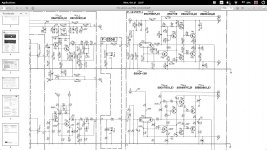
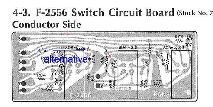
EDIT: I did notice one issue, the Switch Circuit Board (F-2556) is a maze of ground loops. I would suggest a number of strategically placed cuts, roughly like this:

No, unless you want to test whether the fuses work. 😀Do you need to short the Emitter to Collector on all 4 transistors to get zero Bias?
So you have removed the outputs on both sides, i.e. TR11+13 and TR12-14?
You can simulate the B-E junction of each by installing a silicon diode (e.g. 1N400x) in its place, orientation following the arrow in the respective transistor symbol (i.e. anode towards base for npn and anode towards emitter for pnp).
Have you already checked the usual collateral damage? R37/39, R33/35, TR07/09, C05, the feedback side of IC01 (2SA798s are known to fail quite commonly even without any traumatic events)?
You could call the AU-2900 an "accidentally excellent" amp - in wrestling with its modest power supply regulation, they pretty much bulletproofed the preamp circuitry against any supply noise as well. (3900 and 4900 are much the same, but the 5900 had some real issues due to its reliance on a "real" regulator that wasn't too quiet.)
BTW, they never show the value of R57 (R58) in the preamp - mind having a look what it is?
The one thing that this amp (sadly) does not have is output inductors. I would consider winding some, with maybe 4.7 ohms in parallel (often inside).
EDIT: I did notice one issue, the Switch Circuit Board (F-2556) is a maze of ground loops. I would suggest a number of strategically placed cuts, roughly like this:
Attachments

Last edited:
Ha,
The fuses work ok with the shorted output transistors, Great will try the diodes tomorrow, I have measured all the resistors, TR7 as shorted, R33 was smoking and TR11 was shorted. I have read the rest of the transistors (in circuit) and they are reading ok. While I have it open I recapped the main board, and put some nice new BP nichicon's and slimic 2, so once I am sure the voltages are ok I will put in the new transistors.
I checked for R57 and R58 on the preamp and they are blanks, maybe for a different model with the same board, will the inductors make a big difference? I have some from an old amp I could use.
BP nichicons for the coupling caps only, some on the tone control too, but in saying that the quality of those orange BP caps are great like you said, I never really found a bad one of them.
They would certainly make the output more robust against capacitive loading... amps without them tend to have their limits when it comes to stability with certain cables.I checked for R57 and R58 on the preamp and they are blanks, maybe for a different model with the same board, will the inductors make a big difference? I have some from an old amp I could use.
Umm, shouldn't this have gone in the Aiwa 22 thread instead? 😉BP nichicons for the coupling caps only, some on the tone control too, but in saying that the quality of those orange BP caps are great like you said, I never really found a bad one of them.
Anyway, thanks for the info.
BTW, check out the edit on my last post. One for when you get things working.
I replaced C05, Replaced R33, replaced TR07 (2sc1211 ) with an 2n5551 which should be ok replacement. R37 and R39 are both reading 0.6 ohms, actually all four are. I will check out IC01 tomorrow, its just two small signal transistors with emitters soldered together, I found a thread on hear about it, I will give it a read tomorrow. Thanks for your help with this
Great thanks for the tip, I will certainly do that when I have it running. I will have to order some new output transistors from farnell first. Lucky they are easy to get, no expensive SVI chips in this thank god😉I'm sure you know what you wanted to say, but I'm definitely not sure I do!
No, unless you want to test whether the fuses work. 😀
So you have removed the outputs on both sides, i.e. TR11+13 and TR12-14?
You can simulate the B-E junction of each by installing a silicon diode (e.g. 1N400x) in its place, orientation following the arrow in the respective transistor symbol (i.e. anode towards base for npn and anode towards emitter for pnp).
Have you already checked the usual collateral damage? R37/39, R33/35, TR07/09, C05, the feedback side of IC01 (2SA798s are known to fail quite commonly even without any traumatic events)?
You could call the AU-2900 an "accidentally excellent" amp - in wrestling with its modest power supply regulation, they pretty much bulletproofed the preamp circuitry against any supply noise as well. (3900 and 4900 are much the same, but the 5900 had some real issues due to its reliance on a "real" regulator that wasn't too quiet.)
BTW, they never show the value of R57 (R58) in the preamp - mind having a look what it is?
The one thing that this amp (sadly) does not have is output inductors. I would consider winding some, with maybe 4.7 ohms in parallel (often inside).
EDIT: I did notice one issue, the Switch Circuit Board (F-2556) is a maze of ground loops. I would suggest a number of strategically placed cuts, roughly like this:
Still in the learning process, but now know the function of the output inductor thanks to this thread Function of Output Inductor
I will certainly install one on each channel
I will certainly install one on each channel
When you are confident you have found all of the faults, use a limiter lamp on the supply for initial powering (NO OUTPUT LOAD AT THIS POINT).
The lamp should initially illuminate, then dim down significantly.
If the lamp is bright, you still have a fault; the new semiconductors should survive this initial test.
Once you are happy the amplifier is working, let it cool down and set up the quiescent current without the lamp.
You can measure the quiescent current when powering up on the limiter lamp, but the current will be a little low under these conditions.
Ok will make one up, what wattage bulb would you recommend? Just wire it in series with the power input, does it matter if its on the live or neutral, I presume not.
Two more things I noticed:
1. Power supply caps are a skimpy 3300µ throughout the AU-2900/3900/4900 series. Would recommend upgrading these to 6800-8200µ - but watch out for the 1.5 A rectifier diodes (10D1).
2. Driver board F-2554 appears to be shared between all 3 models. As such, there should be spots for the components of the protection / relay driver that could be equipped (I think chunky relays like that are still being made, e.g. Finder 55.12 series; the 2SC1364 might prove more difficult, but I think you could sub in BC337-25/40 with some leg twisting; for 1N34 germaniums just use some small Schottkys if you don't have any). The bad news: It requires an extra, independent 20V~ transformer secondary (presumably they didn't want to put an unbalanced load on the main taps to avoid mechanical hum, though you can certainly try). If you have a ca. 18-20V~, maybe 2-3 VA transformer and a little DIP bridge rectifier on hand, I'd use those and ignore D606.
Just noticed when checking if I had the orientation right from TR07 (Replacing with 2n5551 seems same pinout as (EBC) c1211) I noticed that TR10 which is a A697 5ZD2 which is actually an BCE confused me for a while I thought it was in the wrong way around! anyway I have a pair of neatly glued together with epoxy resin 2 X 2sa1015 with the emitters soldered together encase I need them, IC01 And IC02 are measuring ok in circuit but that is not to say they are not leaking. Will solder in some diodes for testing purposes on the output transistors, will keep you all posted. Thanks everyone for your help
I would be very surprised to find a Japanese transistor that is not ECB or BCE pinout.
Some discussion about potential replacements here. Sure enough, BCE pinout, just like the 2SA697. 2N5551 is EBC.
Some discussion about potential replacements here. Sure enough, BCE pinout, just like the 2SA697. 2N5551 is EBC.
Ok great I finally wired myself a current / bulb limiter, don't know why I waited so long, Put in the diodes to emulate the BE junction as suggested ( and no not shorted Like i suggested it was late 🙂 ), double checked IC01 & Ic02 in diode mode, (BCECB Junctions) and they read as they should (in circuit). soldered in new TR7 (also did TR8 as I like to keep both sides/channels the same) Powered it up with a lamp (the lamp did not go bright) R33 already replaced. All voltages reading fine and spot on compared to the schematic , I will order 4 new output transistors from farnell later. Thanks again everyone for your great support, I will also do the ground mod, and coil on the output for sure, and maybe the protection relay circuit, there sure is space there for it. Do the other models with the same circuit board have the protection circuit, if so I will download the service manual and see what is involved
I'm sure you know what you wanted to say, but I'm definitely not sure I do!
No, unless you want to test whether the fuses work. 😀
So you have removed the outputs on both sides, i.e. TR11+13 and TR12-14?
You can simulate the B-E junction of each by installing a silicon diode (e.g. 1N400x) in its place, orientation following the arrow in the respective transistor symbol (i.e. anode towards base for npn and anode towards emitter for pnp).
Have you already checked the usual collateral damage? R37/39, R33/35, TR07/09, C05, the feedback side of IC01 (2SA798s are known to fail quite commonly even without any traumatic events)?
You could call the AU-2900 an "accidentally excellent" amp - in wrestling with its modest power supply regulation, they pretty much bulletproofed the preamp circuitry against any supply noise as well. (3900 and 4900 are much the same, but the 5900 had some real issues due to its reliance on a "real" regulator that wasn't too quiet.)
BTW, they never show the value of R57 (R58) in the preamp - mind having a look what it is?
The one thing that this amp (sadly) does not have is output inductors. I would consider winding some, with maybe 4.7 ohms in parallel (often inside).
EDIT: I did notice one issue, the Switch Circuit Board (F-2556) is a maze of ground loops. I would suggest a number of strategically placed cuts, roughly like this:
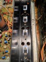
Ok I have the ground mod done, and nearly finished installing the coils, I just have to connect the wires, does it matter if I install the coil before or after the fuses, I presume it does not matter. I only had 470ohm resistors at hand to put in parallel , but they are close enough I presume.
Attachments
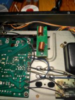
Probably not a real big difference, although usually it is kept before the relay if you're still going for that mod long-term.Ok I have the ground mod done, and nearly finished installing the coils, I just have to connect the wires, does it matter if I install the coil before or after the fuses, I presume it does not matter.
Not nearly. I've never seen more than 22 ohms there, and even that really is considered too high for effective LC resonance damping these days.I only had 470ohm resistors at hand to put in parallel , but they are close enough I presume.
Hi All,
Finally got the transistors installed yesterday evening, and love the sound out of it, Its a keeper for sure, I could not stop listing to it last night. Set up the bias, I already had the 4700uf filter caps installed, as I though you should not go too much higher than the original's but might replace them for UVZ1H682MRD 6800uf nichicon's kind of limited on selection as they are quite close together, 25mm is about max diameter that will fit without having to drill new holes.
Was running some vintage Philips 22RH427 on it. Will check out the phono stage tonight, and finish off the coil installation with the smaller resistor in parallel. Just picked up some infinity QB's with EMIT tweeters during the week, not sure if this little beast will drive them. But it seems to have plenty power for the low wattage, and the transformer is staying cool.
Thanks so much for your great support and help, tips and tricks, much appreciated.
Attachments
avoiding a new thread...
I'm repairing one of these, f2554 board, (had some blown transistors etc.) it powers up but the left channel has rather high DC -100ma- (the other channel 22ma) I cannot figure out where the problem is having checked all I can think of. any pointers? thanks
I'm repairing one of these, f2554 board, (had some blown transistors etc.) it powers up but the left channel has rather high DC -100ma- (the other channel 22ma) I cannot figure out where the problem is having checked all I can think of. any pointers? thanks
And it does not react to the bias adjustment at all? Are you sure it's not oscillation that you're seeing? Maybe check the RC Zobel resistor, R41. Do all the resistors in the output stage check out OK? What replacements have you used for blown transistors, and where from?
- Home
- Amplifiers
- Solid State
- sansui AU-2900