I haven't seen any mention of the loudspeaker's sensitivity. I have some full rangers that can break your lease with an ACA Mini.


Currently using stacked quad 57s wired in parallel so not a particularly easy load. Tend not to go to high levels though. Would also use some DIY 2way speakers, never measured sensitivity of them but I'd hazard a guess at very low 90s or so.
I have a mini-aleph (one pair of mosfets, biased hard, 22v rails, 24 or so watts into 8r) driving them now and it sounds very good..... That's what prompted me to go bigger lol!
I still have warm feelings about my Aleph60 build.
I would say go for the Aleph60!
The sound is fantastic..
If you do it, do it right.. or as in Dutch
Als je het doet, doe het dan goed! 😋
Link to my project:
https://www.passdiy.com/gallery/projects/104/remco-blankesteijn
The only change I did was removing C4.
I would say go for the Aleph60!
The sound is fantastic..
If you do it, do it right.. or as in Dutch
Als je het doet, doe het dan goed! 😋
Link to my project:
https://www.passdiy.com/gallery/projects/104/remco-blankesteijn
The only change I did was removing C4.
I'm for BA-1, BA-2 with the BA-3 front end as well. Built the Aleph 30 and Aleph J many years ago but prefer forementioned ones better. Have both the BA-1 and a crippled F4 with the BA-3 front end making a BA-3. I decided to do this with my F4 eliminating the need for a specific linestage. Most any linestage will drive the BA-3.build BA3
or F4 with your fave semi-high swing preamp in front
no Aleph can be particularly happy with stacked Quads
ok, Alephs 0 can
in fact , Aleph 0 would be bored driving stacked Quads
OK so, I think I will stick with Aleph .... and you guys are making me go for the 60. I have most parts now, but need to do some figuring out on the power supply. I built some cap multipliers for it, and while they have very good performance at 3A load, there is a high frequency ripple at 1.5A that I need to figure out. It looks like oscillation, and right now, I might be better off using a regular CRC supply for each channel. Supply will be 2 x 25V 300VA transformer per channel.
I don't know the burning amps at all.... need to learn more about them, but I have all the boards here now for Alephs, so I think I'll go with that.
I don't know the burning amps at all.... need to learn more about them, but I have all the boards here now for Alephs, so I think I'll go with that.
I'm finally building my Aleph mini, and in my research, I think R8 would be used to fix a DC offset.
I'm installing a pot there even though I attempted to match transistors.
Randy
I'm installing a pot there even though I attempted to match transistors.
Randy
Its been a while since I posted, but things are coming along nicely with this build, although there is lots to do yet.
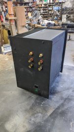
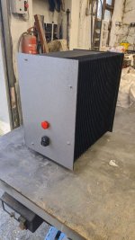
I reckoned that the modushop 5u chassis I had bought would not have good enough dissipation for an Aleph 60. So, I ended up picking up a massive heatsink here through the swap meet here - 380mm x 320mm with 80mm fins on 10mm plate. The thing weighs nearly 8kg. So I am hopeful that it will be big enough and designed with enough dissipation to keep temps reasonable.
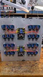
I then set about fabricating a chassis to go around that. The end design is fairly simple, its an upright case (kinda like a PC tower) with the huge heatsink vertical on one side, and on the opposite wall, I have a plate where I will mount the power supplies. I plan on keeping all the AC low down on the chassis and keep it as far away as possible from the rest of the circuit. I'm better at metalwork than I was, but its slow work, and hours go by with little enough to show sometimes. The plan right now is for 2 x 25V 300VA transformers, feeding a cap multiplier, then a CRC bank of 6 x 22kuF per side.
I'll post pics soon (nothing much to see yet as its all in bits at present) but I think it will all work OK. I'm at the stage where I can start wiring parts together, and I think I'll start by connecting the Mini-A boards to the outrigger boards first, then start on connecting up the rest.
I reckoned that the modushop 5u chassis I had bought would not have good enough dissipation for an Aleph 60. So, I ended up picking up a massive heatsink here through the swap meet here - 380mm x 320mm with 80mm fins on 10mm plate. The thing weighs nearly 8kg. So I am hopeful that it will be big enough and designed with enough dissipation to keep temps reasonable.
I then set about fabricating a chassis to go around that. The end design is fairly simple, its an upright case (kinda like a PC tower) with the huge heatsink vertical on one side, and on the opposite wall, I have a plate where I will mount the power supplies. I plan on keeping all the AC low down on the chassis and keep it as far away as possible from the rest of the circuit. I'm better at metalwork than I was, but its slow work, and hours go by with little enough to show sometimes. The plan right now is for 2 x 25V 300VA transformers, feeding a cap multiplier, then a CRC bank of 6 x 22kuF per side.
I'll post pics soon (nothing much to see yet as its all in bits at present) but I think it will all work OK. I'm at the stage where I can start wiring parts together, and I think I'll start by connecting the Mini-A boards to the outrigger boards first, then start on connecting up the rest.
tower sinks are not efficient as same amount of Al, cut in half and arranged in depth (in usual way as on, say, Modushop cases)
just count on that
just count on that
Yeah, but I really really don't want to do that. First off, I have no way of cleanly cutting a heatsink that deep, and secondly, the chassis is already built around this now..... so naturally the resistance to change is strong!!tower sinks are not efficient as same amount of Al, cut in half and arranged in depth (in usual way as on, say, Modushop cases)
just count on that
I think I'll try it and see first how it goes.
not pushing you to change anything, just saying
in the end, you can always make nice looking Babysitter platform
in the end, you can always make nice looking Babysitter platform
my OCD is caps temperature
that's why I'm using Babysitter with all my amps during Summer
even when I'm forced to turn on AC, I'm using it just to prevent sweating of my forehead ( can't see then, spectacles), not to cool my amps
that's why I'm using Babysitter with all my amps during Summer
even when I'm forced to turn on AC, I'm using it just to prevent sweating of my forehead ( can't see then, spectacles), not to cool my amps
Understood. Cap temperature is just as important as transistor temp. I'll have mine mounted on the opposite side of the case, so it should be 20degC cooler there. But if it is bad I can add a fan if needed
Progress has been made!
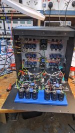
So this is a dual mono in one chassis build. Separate transformers, cap multipliers, reservoir bank, the chassis itself and IEC connector/power switch is the only thing shared.
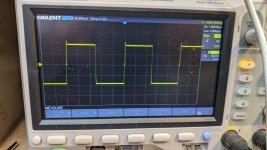
It's not very often that you put a build like this together and it all just works out of the can..... But this did just that. Dead silent, no hum or hiss, DC offset less than 50mV. I'm getting around 420-470mV over each source resistor (1r), it's pulling around 2.5A on each rail (per channel). Sounds great out of the can, very dynamic and smooth. Square wave looks good (the one shown was at 18v I think from memory) and there is just a little ringing there.
I'm getting a little lower power than possible, 45W per channel into 8 ohms resistive load. I used 25v transformers but the cap multiplier does drop a few volts. I was getting about 30V rails. Heatsink is at 47degC, which is about 30deg above ambient in this room today.
After a bit of soak testing I'll go back and check AC gain, and maybe look at dropping the DC offset a bit more. For now I'm just happy that it's working and sounding as good as it is. I'll need to go back and cross check all measurements, verify everything, tidy up wiring, clean the chassis off and plenty of other bits of tidying up.
Thanks to all who gave guidance along the way, especially those who responded to my want and for some mini-A boards, and of course @Nelson Pass for the design!
If anyone sees anything glaringly wrong, please let me know!
So this is a dual mono in one chassis build. Separate transformers, cap multipliers, reservoir bank, the chassis itself and IEC connector/power switch is the only thing shared.
It's not very often that you put a build like this together and it all just works out of the can..... But this did just that. Dead silent, no hum or hiss, DC offset less than 50mV. I'm getting around 420-470mV over each source resistor (1r), it's pulling around 2.5A on each rail (per channel). Sounds great out of the can, very dynamic and smooth. Square wave looks good (the one shown was at 18v I think from memory) and there is just a little ringing there.
I'm getting a little lower power than possible, 45W per channel into 8 ohms resistive load. I used 25v transformers but the cap multiplier does drop a few volts. I was getting about 30V rails. Heatsink is at 47degC, which is about 30deg above ambient in this room today.
After a bit of soak testing I'll go back and check AC gain, and maybe look at dropping the DC offset a bit more. For now I'm just happy that it's working and sounding as good as it is. I'll need to go back and cross check all measurements, verify everything, tidy up wiring, clean the chassis off and plenty of other bits of tidying up.
Thanks to all who gave guidance along the way, especially those who responded to my want and for some mini-A boards, and of course @Nelson Pass for the design!
If anyone sees anything glaringly wrong, please let me know!
Attachments

AC gain check done last night:R12
easy - when (with signal - say 1KHz,and load connected) AC voltage across R28 is same as across R27, Aleph CCS current contribution is 50% of sum output current
also called Aleph CCS Gain, though - I always found initial Papa's explanation confusing
but, I'm easily confused, no biggie.... even started enjoying that as permanent state
Drove 100hz signal to give a 10V output into 8r resistive load.
Average voltage across the "lower" source resistors (connected to the negative rail)- 421mVAC
Average voltage across the "upper" source resistors (connected to the positive rail) - 490mVAC
Unless I have this backwards, this means I have ~45% or so which should be the sweet spot.
- Home
- Amplifiers
- Pass Labs
- Sanity check - Aleph 60 build