Hi all,
Recently I revisited a mini-aleph I put together years ago from a BrianGT set of boards. Anyway to cut a long story short, after a few bits of fixing up I was pretty amazed at how good the amp sounded. It got me thinking about what would a higher powered version sound like, and so I began on a journey of reading and finding the parts needed to build an Aleph 60. I managed to get a few BrianGT boards (thank you to those who searched their parts bins), plus the extra output boards and I have most parts now to assemble it. So there is a monumental amount of Aleph info out there, and its all jumbled in a million different threads, which makes it hard to find some answers - so I'm being cheeky and asking here some fairly basic questions which I'm hoping someone who has lived and breathed the aleph air can probably answer in their sleep:
1. I plan to build with 2 separate supplies in a 5U modushop chassis and bias it to stay just below 60degC.....
2. I have 2 of 2x25V 300va transformers lined up, and planned on using a pair of cap multipliers as supplies (planning on the mark johnson/prasi boards with 2sc5200/2sa1943 and the minimum possible voltage drop, about 2.5V I think to minimise dissipation). If the cap-mx doesn't work out, I have regular CRC boards I can use.
3. I think I can use the BrianGT mini-aleph boards with pretty much no changes on the main boards, and then just add the satellite boards populated with the matched mosfets (irf240) and 1r0 source resistors.
Does this sound correct to the experts here?
2. just be sure to have significant number of uF after cap multiplier; CM is practically electronical analog to physical choke, so you still need cap reservoir after
Fran, you rail voltages may be a bit low for 60W (into 8 ohms); you'll probably get 50-ish watts. Unless you really need the 60W
this isn't a bad thing since it lowers the dissipation. A stereo A60 with ~160W per channel (+/-35V rails, 2.2A bias) will be a challenge even for a 5U chassis.
There Alephs are all pretty much the same so just build according to the schematics and you should be fine.
In case you haven't seen this post, Papa had some suggestions on the Aleph:
https://www.diyaudio.com/community/threads/the-aleph-design-reloaded.267857/#post-4184920
Cheers,
Dennis
Great stuff, many thanks all.
@Dennis Hui Yes, I am worried about the dissipation alright. Past experience means I am a believer in running them hard for the best sound but there is a limit!!
@Zen Mod - I planned on 4 x 10kuF per channel after the CM. But maybe I am better off going to 60kuF per channel?
Fran
@Dennis Hui Yes, I am worried about the dissipation alright. Past experience means I am a believer in running them hard for the best sound but there is a limit!!
@Zen Mod - I planned on 4 x 10kuF per channel after the CM. But maybe I am better off going to 60kuF per channel?
Fran
You can run as Aleph 5 or Aleph 60 and get the same power output. It's only a few changes to values on the boards. You run the individual 240's hotter as aleph 5, but overall total is similar. If your BrianGT boards can handle the MOSFETs for Aleph 5, that's an option to consider. Get the service manual for the A5 and you'll have what you need. Also check the "design reloaded" for a few tweaks.
Dennis and ZM have covered the PSU questions. I was going to say the same about transformer voltage / power out drop with cap Mx.
Dennis and ZM have covered the PSU questions. I was going to say the same about transformer voltage / power out drop with cap Mx.
OK, great advice there, thank you for that. I'll look up the A5 and see what the differences are.
I do have some whopper transformers around 37VAC, but I think thats probably a bit high, and certainly pushes me beyond the heatsinking I have. I think for this build its probably appropriate to go with the 25VAC transformers, 50WPC will be more than enough.
I did some searching but I didn't find very much on other people using a cap multiplier with the alephs (or any class A). Maybe I'm on a fools errand? But my thinking was that surely the reduction in ripple would be a good thing. Maybe though it introduces other issues?
ppl are using CMs and they're happy
me personally, never liked them ....... but I'm often stubborn and always heavily subjective
me personally, never liked them ....... but I'm often stubborn and always heavily subjective
I am using the SLB version of capacitance multiplier in my F6 and in an external chassis for my VFET lottery amp. Both use an extra bank of bulk capacitance after the CapMx and are entirely hum free.
There are also other ways to do a good PSU. My Aleph J uses dual-mono CRCRC supplies, and also sounds wonderful.
There are also other ways to do a good PSU. My Aleph J uses dual-mono CRCRC supplies, and also sounds wonderful.
I used one on a Class AB amp, with 4x15kuF after it (shared between both channels) and there was a significant lift in performance, so I thought it was worth a try at least anyway.
We are all shades of stubborn. If we weren't we wouldn't have gotten by the first case of beating hum!
We are all shades of stubborn. If we weren't we wouldn't have gotten by the first case of beating hum!
@rhthatcher - so an Aleph 5 has 2 x 3 output mosfets running at 1A each with 35V rails, where the the Aleph60 has 2 x 6 outputs but biased lower at .37A - I think I have that right? The front end is essentially the same.
What was the advantage in running 6x rather than 3x? Certainly makes it easier to fit on a heatsink.
What was the advantage in running 6x rather than 3x? Certainly makes it easier to fit on a heatsink.
Sorry - I misread the Aleph 5 schematic - its 0.5V across 1r0 (not 0r47) so half an amp, not the 1A mentioned above.
Hi woodturner-fran:3. I think I can use the BrianGT mini-aleph boards with pretty much no changes on the main boards, and then just add the satellite boards populated with the matched mosfets (irf240) and 1r0 source resistors.
My first Pass amp actually was a Mini Aleph built on BrianGT boards.
I did build a CLCC power supply (using a BrianGT PSU PCB) with 33mF - 2.5mH at 0r44 DCR - 66mF. Didn't try a Cap Multiplier, but the CLC provides very little ripple.
I did only use one pair of outputs and did use IRFP140, first with 19V and 2.2A, then with 24V and 2.0A. The 19V/2.2A sounded slightly better to me.
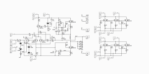
But, long story short, you can use the BrianGT boards without changes to connect several output boards for an Aleph 60. I have attached a .pdf covering an Aleph 60 that I think I got from BrianGT's web site (chipamp.com) at the time. The main difference, I think, between Aleph Mini, Aleph 30, and Aleph 60 on the BrianGT board is how the Aleph current sense resistors are configured.
I later converted my Aleph Mini into an Aleph J (with a single pair of IRFP140s at 24V/2A), and that one sounded great. Because on the BrianGT board there is no provision to cascode the JFETs of the differential pair, and the board is tightly packed already, so it's difficult to add, this would limit you in terms of rail voltages to approx. +/- 30V.
Best regards, Claas
Attachments
Great stuff - thank you all so much, it makes it SO much easier to pull this together.
So copied from here it looks like:
R6 may be used to help correct offset if there is a mismatch in Q1 and Q2. You don't need it if you get a good match.
R12 sets the AC current gain. You'd be at 50% with 1K
R13 fine tunes the bias in the output stage. The higher the value the greater the bias.
R17 is a protection circuit part that sets the Q6 current when the protection kicks in. 392R has been used before. I used 1K and 1k2 for R21.
And attached is the schematic for ease of reference. I'm putting this here for my own benefit as much as anything!!
Attachments

Thank you Claas and Fran for posting the schematics info. I had completely forgotten that Brian's PCB has some different parts numbering.
Cheers,
Dennis
Cheers,
Dennis
Some further info on the "tbd" values. As I get more info, I'll post more.
I don't have a value/range of values just yet for R6
People seem to have experimented with R12 going between 680R to 1k. So a 1k pot is probably not a bad suggestion for experiments
R13 - default value seems to be 47k5, and you see from this value up to 200k mentioned in the older treads. So probably a 200k pot preset to 47k is a good place to start.
R17 - this is a bigger range - some are 100R, and you'll see above someone else used 392r. Needs some experimentation, and of course some leave out the protection circuit completely.
R12
easy - when (with signal - say 1KHz,and load connected) AC voltage across R28 is same as across R27, Aleph CCS current contribution is 50% of sum output current
also called Aleph CCS Gain, though - I always found initial Papa's explanation confusing
but, I'm easily confused, no biggie.... even started enjoying that as permanent state
@Zen Mod - that is very easy, and easier to set on these boards maybe than the newer ums designed ones.
So I'm still in a quandary about building Aleph 5 vs Aleph 60. As far as I can see the key difference here is 12 mosfets vs 6 per channel, and different source resistors, then do the 3 settings of bias, AC gain and offset. I snagged a big heatsink with 80mm fins from the swap meet (340x380mm from memory) so that would have bigger dissipation than the 5U modushop case. I think I will end up around 27-30V rails under load so as pointed out above I won't hit 60W, but no matter.
The key question as always - "which will sound better" impossible question I know!!


- Home
- Amplifiers
- Pass Labs
- Sanity check - Aleph 60 build