I'm not a fan of a bridge amp made from a single amp.
Saving a few low-power transistors is not worth it.
The difficulties of wiring such a board are much more significant.
Preferably two amplifier stages each on a separate board connected already in a bridge connection.
And a three-stage amplifier is a bad idea if the same and even higher amplification can be done directly with two amplifier stages.
Two amplifier stages are always more broadband than three. And that means high frequency and deep negative feedback.
Got it, basically its a 2 in 1 design, if we clone input stage transistors it will become 2 amps.
Hi Sandy,
I am going to order VFA P FET 1-1-3.4 V3.3 for PCB.
Is built before or tested PCB.
You have built this amp with some hardware test?
I am going to order VFA P FET 1-1-3.4 V3.3 for PCB.
Is built before or tested PCB.
You have built this amp with some hardware test?

I found a pea on the remorseful version.
I will upload a corrected version, please wait a moment.
I will upload a corrected version, please wait a moment.
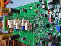
The height of BJT is different. It can't be suppressed from the top of the PCB with screws. Is there any good way? I'm sorry I am not good in English, so I used Google Translation
I apologize for the delay, but I want to clarify a few more details about the protection and thermal compensation of the quiescent current.
But I'm working on it.
But I'm working on it.
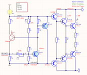
The idea is to have 2 two trimmers to adjust the quiescent current.
One for 25C and the other for high temperature.
The position of Rtr1 does not affect the current through the terminals when the radiator is at room temperature, because the voltages at points "A" and "B" are the same.
So, during initial start-up, we set Rtr1 to the maximum value and with Rtr2 we adjust the current through the terminals.
In this case, there will be a re-regulation and during heating the current will decrease, then with Rtr1 smoothly with a wait we raise the current to the required one.
Attachments


Hi Sandy,
Thanks for continues working to improve VFA P FET version.
Need details setting related Rtr 1, Rtr2, & Rtr3.
& how can set if dc offset higher in out point.
Point A & B in above & privous post is different position.
Set of bias & TP1 & T2 terminal need more clear.
Thanks for continues working to improve VFA P FET version.
Need details setting related Rtr 1, Rtr2, & Rtr3.
& how can set if dc offset higher in out point.
Point A & B in above & privous post is different position.
Set of bias & TP1 & T2 terminal need more clear.
I will also fix the other version of the board with 2N5401/2N5551 and upload both projects.
And I will write you in more detail about the setup method.
It has short notes on the scheme.
|The first trimmer Rtr1 simply puts the op amp into mode.
It is purposely made to adjust within small limits so as not to affect the sound.
With a cold amplifier, Rtr2 does not affect the quiescent current.
The base voltage of T20 and the collector of T15 are equal.
To make them equal, if necessary, we change R25.
I need to check these values live.
After warming up the amplifier, we use Rtr2 to set the same quiescent current as when the amplifier is cold.
Rtr2 adjusts only the temperature coefficient we need.
For DIY projects where everyone will put whatever transistors they can find and feed it with whatever voltage they need, this complicated setup makes sense.
An operational amplifier can be in 3 types of cases DIL8 SO8 SOT23-5
Added a second trimmer to adjust quiescent current with it at high temperature.


Attachments
The difference with the previous project is the 2N5401/2N5551 transistors


Attachments
Thanks sandy updated both version with so many option parts selection in one PCB.
So which one do you prefer is KSC1845/KSA992 is V3.32.
Or 2N5551/ 2N5401 is V3.42.
So which one do you prefer is KSC1845/KSA992 is V3.32.
Or 2N5551/ 2N5401 is V3.42.
I purposely made two types of boards for base-centered transistors and collector-centered transistors.
Everyone should put what they have, and according to the power supply voltage used.
Everyone should put what they have, and according to the power supply voltage used.
- Home
- Amplifiers
- Solid State
- Sandy - Power VFA