irfp240/irfp9140 are a better matched pair than irfp240/irfp9240, if the lower 100Vds limit is acceptable.
I finally got around to my dcb1.
I am using a Tent Labs relay volume control with TX2575 resistors and TX2575s in the B1 as well. I am very pleased with the sound. Pretty much everything that has already been said about this buffer I am in agreement with. I must also add that the Tent Labs relay volume control sounded very nice as well on it's own and the buffer helped with the low freq output, keeping the mid and highs unchanged.
I am using 5w 10 ohm resistors as per the 200ma hot rod specs, but am now considering the 600ma upgrade as there was no noticeable temp change after running for several hours. I am using the 12mm thick alu chassis as heatsinking and really could not detect any temp rise over 3 plus hours.
Got 1 and 1.2 ma of set. Will need to recheck this and all other voltages as.dmm battery died.
Brad
I'm getting small-minded, I guess. And there are a couple of things I've unforseen.
After changing my 220Rs to Takman carbons and living happily thereafter for some time, as a beginning DIYer, of course, I couldn't sit still. I made changes again. Replaced an Alps pot to a cheaper DACT type one, just to see what it gives. It sounder more "veiled" and letting it play for a week or so improved things just a tiny bit.
So I thought, ok, maybe that's a resistors and pots combo, that is not working right. And as I had 4x TX2575s by hand, and read so many good reviews, I replaced takmans.
Now the sound got more transparent, but lean and rather bright. That is ok, as I should wait for these resistors to burn in and I could always check what they sound like with Alps pot.
But there's one thing that bothers me. How all this desoldering/soldering activity is affecting the board? It shouldn't do any good. And at one point I've got parranoid that maybe my joints are not that clean now, hence a rather bright sound.
Reading "..symmetrical psu b1.." thread I've found a recommendation for using this thing: 310-43-164-41-001000 Mill-Max IC & Component Sockets
I don't get 64 contacts thing. Shouldn't it be just 2 for resistors? Is it the same thing as this one: Farnell Export
All this pots and resistors trial is getting tiring. But I'm still considering LDR attenuator, hot rodding and final resistors ajusting.
The pins can be removed from those 64 pin sockets and used individually. Also, hottrodding is recommended, LDR pot is good, but requires a lot of implementation as it needs a power supply all of it's own, perhaps a gimic really. Keep the TX2575s - they are simply better than carbon films - better to change the value to arrive at preferred sound, not technology!
I now have DCB1 blue (hotrodded) with good components and PRP resistors, Mezmerize channel switchers, R-core transformer, remote volume controlled LDR pot. All of this stuff to make a really well designed, tiny circuited, silver wired and low component pre-amp. Is it worth it? Probably...?!
I now have DCB1 blue (hotrodded) with good components and PRP resistors, Mezmerize channel switchers, R-core transformer, remote volume controlled LDR pot. All of this stuff to make a really well designed, tiny circuited, silver wired and low component pre-amp. Is it worth it? Probably...?!
Hi siberia,
You could use those sockets until you find the ideal parts for your B1.
Word of advice, I've been there as deep as you are now and I didn't like Diy-ing at that moment, like a neverending story, not enjoyable at all. Maybe it's time to do something that hasn't anything to to with electronics, just to get some distance 🙂
Best wishes, Erik.
Lucas & Erik that's encouraging! Thank you. I have no doubts about the design of this preamp. It has already so much more then I expected. And yes, you are right, I should keep TX2575s and a bit of distance to all this stuff. Then go get LDR pot and to see if anything's misssing. Uriahs suggestion was to use a LM317 to get 5V from DCB1's PSU.
I have only one pair of inputs at this time. Not sure if I want to add a swtich with all additional wiring and components. Although it could be useful as I use two sources.
I have only one pair of inputs at this time. Not sure if I want to add a swtich with all additional wiring and components. Although it could be useful as I use two sources.
For a pure buffer only build (no volume pot) are there any considerations or additional parts I should use?
No. As it is.
Thanks Salas, so there is no need to parallel 220k resistors with 20k underneath the board to get the input impedance within the desirable range?
I read this here:
http://www.diyaudio.com/forums/blogs/rodeodave/509-my-salas-hotrodded-dcb1-build.html
After listening for a couple of tracks tonight, I decided it was horrible enough, to start looking for the source of evil.
I've measured film resistors two of them were 120R instead of 220R. Is it possible they were fried while soldering? It was a longer process than usual, due to amateur desoldering.
I've measured film resistors two of them were 120R instead of 220R. Is it possible they were fried while soldering? It was a longer process than usual, due to amateur desoldering.
Siberia, an interesting point about the DCB1:
The B1 buffer, as designed by Nelson Pass, was very similar to this DCB1, but had capacitors in the circuit, done away with in this version by way of being DC coupled. Other than that, the original resistor choice by Papa Nelson was quite different, and after experimentation, new values were selected. Those 220R resistors were originally 1K, but several opinions suggest that the bass is tighter with touch more drive with the lower value. So, whilst I think I would stick with 220R if possible, it is an arbitrary decision, and why I suggested value swapping to shape the sound, as opposed to trying out carbon films etc. That's Nelson Pass's advice too, and he's a bonifide genius, so...
The B1 buffer, as designed by Nelson Pass, was very similar to this DCB1, but had capacitors in the circuit, done away with in this version by way of being DC coupled. Other than that, the original resistor choice by Papa Nelson was quite different, and after experimentation, new values were selected. Those 220R resistors were originally 1K, but several opinions suggest that the bass is tighter with touch more drive with the lower value. So, whilst I think I would stick with 220R if possible, it is an arbitrary decision, and why I suggested value swapping to shape the sound, as opposed to trying out carbon films etc. That's Nelson Pass's advice too, and he's a bonifide genius, so...
After listening for a couple of tracks tonight, I decided it was horrible enough, to start looking for the source of evil.
I've measured film resistors two of them were 120R instead of 220R. Is it possible they were fried while soldering? It was a longer process than usual, due to amateur desoldering.
Sounds like mistaken marking (very weird if so). Demand change if they measure 120R OUT of circuit. Also are those put differently between channels? Input or output positions?
Siberia, an interesting point about the DCB1:
The B1 buffer, as designed by Nelson Pass, was very similar to this DCB1, but had capacitors in the circuit, done away with in this version by way of being DC coupled. Other than that, the original resistor choice by Papa Nelson was quite different, and after experimentation, new values were selected. Those 220R resistors were originally 1K, but several opinions suggest that the bass is tighter with touch more drive with the lower value. So, whilst I think I would stick with 220R if possible, it is an arbitrary decision, and why I suggested value swapping to shape the sound, as opposed to trying out carbon films etc. That's Nelson Pass's advice too, and he's a bonifide genius, so...
If he had problems with the 220R value itself in the context of his system, he would have so with his previous same value parts also, simple logic dictates.
If he had problems with the 220R value itself in the context of his system, he would have so with his previous same value parts also, simple logic dictates.
Well, if he had carbon 220r in place and (as he states) liked them, but swapped them for 120r metal film anyway (thinking they were 220r) and doesn't like them, it could either be the metal film he doesn't like, or else the values, right? My guess is it's the values, or else something completely different. Everybody seems to love those Texas resistors.
Problem is he was targeting same value and discovered another in some. If its really so, its apples to oranges and in mixed places probably also.
Lucas's DCB1 Pre-Amp is Finished!
Anyway, I finished my pre-amp at long last this evening. Still a few touches of paint to add here and there, but electronically, it's finally together...
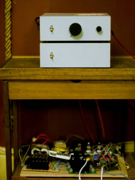
Now, underneath there in that mess is a fine fine DAC, I swear!
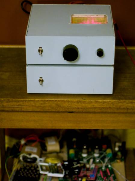
On switch, volume control, 4 channel selector. Volume off marker is the infra-red receiver lens.
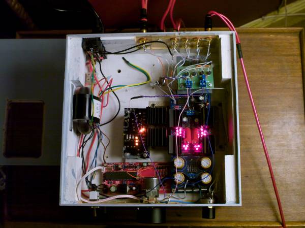
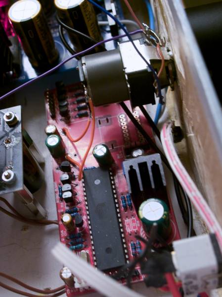
Under the hood.
The audio signal is all in this photo. It's a lot of electronics to make the signal short and with few components.
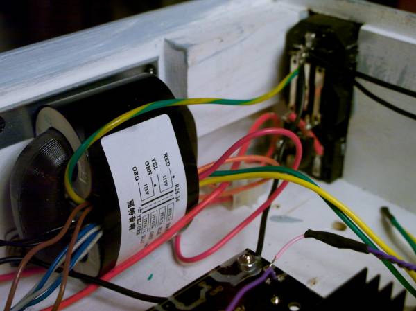
I bought a nice R-core from Hong Kong with all of the values I needed. It's pretty good.
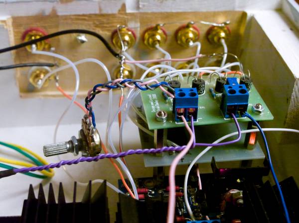
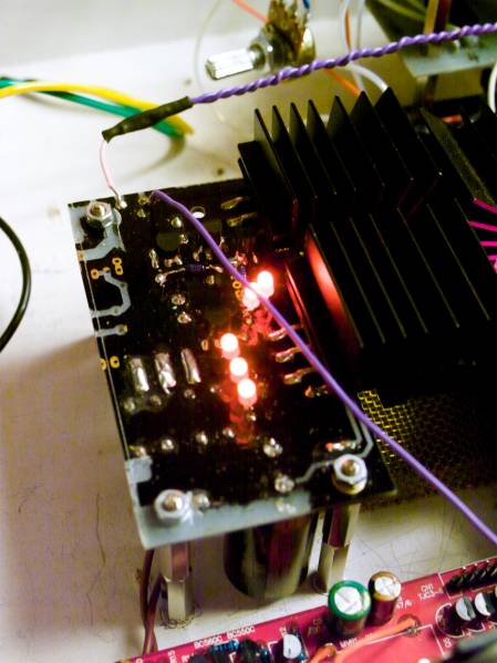
The DCB1, with some nice components.
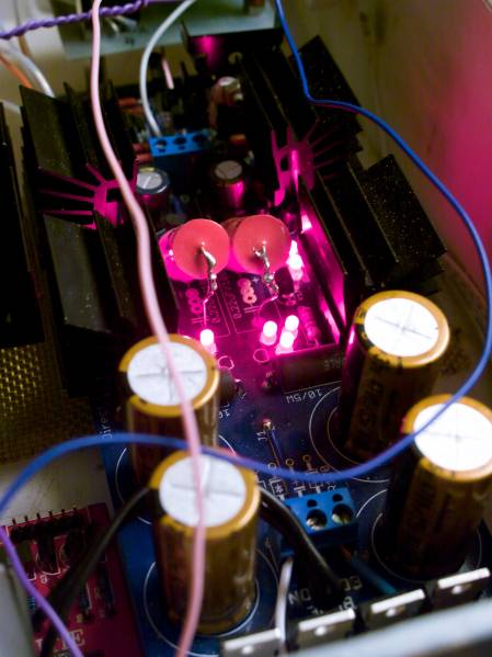
The Lightspeed LDR attenuator leds get their juice from this Salas reg I made from an old Mezmerize board. The Mez selectors are under the LDR board too.
The Remote control is actually electrically isolated from everything, other than the transformer of course. I had to remove the pot and motor from the board, and the pot had the weirdest wiring arrangement, so I connected the motor to a lovely old Alps pot from an old amp I had taken to bits. It works beautifully. I didn't bother with the remote channel selector - no need!
So, that's it.
Anyway, I finished my pre-amp at long last this evening. Still a few touches of paint to add here and there, but electronically, it's finally together...
Now, underneath there in that mess is a fine fine DAC, I swear!
On switch, volume control, 4 channel selector. Volume off marker is the infra-red receiver lens.
Under the hood.
The audio signal is all in this photo. It's a lot of electronics to make the signal short and with few components.
I bought a nice R-core from Hong Kong with all of the values I needed. It's pretty good.
The DCB1, with some nice components.
The Lightspeed LDR attenuator leds get their juice from this Salas reg I made from an old Mezmerize board. The Mez selectors are under the LDR board too.
The Remote control is actually electrically isolated from everything, other than the transformer of course. I had to remove the pot and motor from the board, and the pot had the weirdest wiring arrangement, so I connected the motor to a lovely old Alps pot from an old amp I had taken to bits. It works beautifully. I didn't bother with the remote channel selector - no need!
So, that's it.
Last edited:
Looks so 50's English its appealing in a weird way to me. What about all those boards on low shelf? Parallel cap PSU arrays and R-Core.
*Ah, OK, you answered later on. Very individual dcb1 I must admit. What is the system it serves?
*Ah, OK, you answered later on. Very individual dcb1 I must admit. What is the system it serves?
Looks so 50's English its appealing in a weird way to me. What about all those boards on low shelf? Parallel cap PSU arrays and R-Core.
It's a 2x TDA1541a DAC with shunt regs designed by this Greek fella - you might know him! Pretty overkill implementation inspired by this German dude Oliver Mai. Tube output stage that this Polish guy Lukas Fikus goes nuts for.
The DAC is freakin' lovely. I swear! Now I've just got to box the thing up 😕
Last edited:
- Home
- Source & Line
- Analog Line Level
- Salas hotrodded blue DCB1 build