Its not crucial to have exactly same idss pairs in channels. They can be say 9mA in L and 8mA in R. But if much different, THD measurements will noticeably change between channels. Especially at high signal levels.
I tested a pair of 10ma Idss (one self biasing the other) and a pair of 6 ma Idss at 0.5v input 1khz signal using my Focusrite. I got THD of .00079 for both Idss pairs. . Perhaps THD is much higher at higher signal levels which I cannot check properly with my equipment.
However, I also did an additional test. I used a 8ma as follower with no source degeneration and a 9ma selfbiased with source degeneration of 3.5r to give me a near zero DC offset. At 0.5v, THD was .00068. So far these are the lowest readings I have got. H2 was a bit higher than H3 without any degeneration in the first two cases and and lower than H3 in the third case with the 3.5r degeneration. I tested twice but still wonder whether the results are plausible.
Thanks. nash
As a resistance value yes it can but the many interconnects will also add significant capacitance that demands current the more HF the signal goes. Buffer all of them outputs with 100R in-line resistors and try results. I would better use the DCG3 high constant current biased (Class A SE) output stage preamp in this case (but it has gain too).
I had built up a DCB1 (Mezmerize) black GB board hoping to use the shunt psu for a test of other things and spent an evening measuring LEDs. I had a quad of matched 2SK170 and picked out a pair of N and P mosfets from a batch I bought from Tarasque long time ago - measured and matched, although they are not matched N-P (matched NN and matched PP) but not that far off based on the stickers (4040/4040 and 4086/4087).
I couldn't figure out why I had such an imbalance between + rail and - so I merely swapped out red LED for green on one and red LED for blue on the other and left it with about 0.1V (100mV) diff.
Now I know, thanks to 6L6 that blue LED are no-no as a vref so out it comes and so does the green one on the other side. I put in 2 new LEDs on both sides (5 each side) and I get a full 1.0V difference between the + and - rails (10.7 and -9.7).
Now when I measure the Vdrop from ground to LED legs and do the math, I see a consistent 2.0x V across the + side LEDs and 1.8x V across the - side LEDs. I found this disturbing because the LEDs all came from the same bag, same batch that I had gone through so much trouble to measure and match.
When I measure Vdrop across a single LED in circuit, I see the same thing. MMeter shows 2.0V on the + side LED and 1.8V across the - side. Completely puzzled at this point because I fully expect to see 1.8V through an LED, not 2.0V.
Just measuring the PSU at this point. BJT (550 and 560) are C-grade hFE (550CTA and 560CTA) if that matters.
This is my first DCB1 so I wasn't sure how close the rails should be but I suspect after reading some of this thread that 1.0V is far beyond normal.
Anyone have ideas on what I should start replacing or measuring?
Mezmerize classic has inbuilt different levels of current sourcing between Vrefs. Not your fault. That's by design. It was to tweak its sound for the better when running low PSU bias sans sinks. Blue Hypno that was for hot-rod, and the Mez 2018 "ten years after" reissue after nobody was planing to run a Mez naked anymore, do not have that tweak. This is the Hypno thread so you wouldn't meet significant rails imbalance references in the posts anyway.
If you want it perfectly symmetrical (especially suitable when also using it as a general supply) do the "leg trick". That will set it to modern mode. See point 6 in the following link: https://www.diyaudio.com/forums/the-diyaudio-store/213998-mezmerize-b1-buffer-preamp-21.html#post5406253
If you want it perfectly symmetrical (especially suitable when also using it as a general supply) do the "leg trick". That will set it to modern mode. See point 6 in the following link: https://www.diyaudio.com/forums/the-diyaudio-store/213998-mezmerize-b1-buffer-preamp-21.html#post5406253

Thanks Salas! It does look like that's the version I have. I will build the 2008 Mezmerize the way it was intended and then use the Hypno board for shunt psu and modify the leg as directed. 


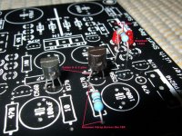
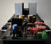
The small heatsinks are temporary as are the 20R resistors. When it's ready to be installed properly I will mount to chassis and replace with parallel 18R resistors.
One question - am I right that the Alps pot goes in with the shaft in the middle of the board and not sticking out? It seems to be meant that way based on the silkscreen. If I mount it facing the wrong way it will mean the pot turns the wrong way or will it still work that way?
Last edited:
Thanks Salas! It does look like that's the version I have. I will build the 2008 Mezmerize the way it was intended and then use the Hypno board for shunt psu and modify the leg as directed.
View attachment 838244
View attachment 838245
The small heatsinks are temporary as are the 20R resistors. When it's ready to be installed properly I will mount to chassis and replace with parallel 18R resistors.
One question - am I right that the Alps pot goes in with the shaft in the middle of the board and not sticking out? It seems to be meant that way based on the silkscreen. If I mount it facing the wrong way it will mean the pot turns the wrong way or will it still work that way?
Yes it was meant to point the shaft in the middle of the board. From there usually ties to an extension rod. If reversed on the board it will also open volume anticlockwise.
My Balanced HOTROD DCB1
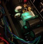
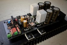
Here is my HotRod DCB1!
It is a balanced version:
1. dedicated transformer at 80VA for each channel.
2. the hotrod resistors are 1.5Ω.
3. Russian Teflon type for the LED bypass caps at o.22uF.
4. I include both SE and XLR inputs & outputs.
5. The chassis is 3U; everything fits a bit tightly. The temperature is about 42-45C around the FETs with no top lid.
6. DC offset is -1.1mV on left channel and -1.0mV on the right.
One little problem here:
I got a green LED on one side! (one near the hotrod resistor)
Is it a defective amber LED that has turned green magically?
......or Mouser gave me a green LED in a bag of 50 amber LEDs?
Question: should I replace the green LED with an amber one?
The green LED channel is about 2C degrees higher. Is it related? Is green LED noisier?
A quick testing shows good SQ. More 3D, soundstage is wider, more dynamic and more everything.
I have a clone note to go with my hotrod DCB1; I will turn it into a balanced version as well. It is easy to upgrade with just a few extra parts.
Now enjoy the music!
Attachments
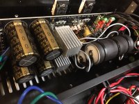
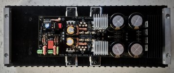
A nice "full" looking build with clever local sinking solutions. Congratulations.
If it was a product to distribute, the silver sinks only support by big resistors legs would probably not survive bad shipping vibrations. Eventually some succumbing to metal fatigue. Just saying because its an irrelevant thing here. The bridge diodes are isolated I hope.
Most possibly a mix up happened and you got a green among amber leds. I have seen red glowing orange from electrical abuse soon before expiring, but I don't know if amber goes green and continues. Little more temperature around it shouldn't be a reason. Original green is not significantly noisier than amber but it has little higher Vf.
Better change it to amber so to be sure it is what it has to be. Or what it used to be.
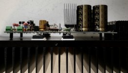
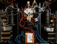
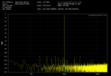
measured the hotrodded dcb1 today.... all hum at between -100 and -110 dB ( other channel is lower )..... Amazing SNR and THD specs....
Thanks again Salas. And Nelson!!!! Crazy good unit. PIC taken at full and about half way on the volume control
Thanks again Salas. And Nelson!!!! Crazy good unit. PIC taken at full and about half way on the volume control
Attachments

Last edited:
That is low enough harmonic noise for the ear not to detect any but it can be eradicated further when equipped with QuantAsylum gear to experiment with trafo orientation and cable dressing while watching it. Or to also add some strategic shielding even. This THD screenshot (dated June 2009) is from my prototype two plastic box DCB1.
Attachments
Thanks. I have the speaker protection circuits installed.
The DCB1 has low output offset. The connected DAC is higher. The end result is not excessive ( 70 mV at the speaker on one channel. ) I'd rather it were lower.
I suppose review of the DAC would be a good idea, since the other channel has comparably low DC offset. ( The DAC is a UA 2192. Very nice analogue sound )
- Home
- Source & Line
- Analog Line Level
- Salas hotrodded blue DCB1 build