Measured voltage drops across the current setting resistors are OK, do DC mV offset measurement across each audio output also. To post a picture press the "Go Advanced" button under the reply frame and use the "Manage Attachments" menu.
http://www.diyaudio.com/forums/attachment.php?attachmentid=408645&stc=1&d=1395959331
Here it is , I hope. Please review how to measure dc offset at outpost.
Here it is , I hope. Please review how to measure dc offset at outpost.
Attachments
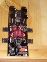
Looks very well put together. But don't run it for more than minutes without sinking on a metal surface or real sinks at this current setting. Don't forget it needs insulation pads on the MOSFETS backs when you will do the sinking. To know DC offset you just need the DMM on DCmV range with black probe on center pin of the out Molex and red probe to L, then to R.
DC offset: .004v and .003v
Using inexpensive Radio Shack 25.2 VAC with center tap. 12v to each side.
Using inexpensive Radio Shack 25.2 VAC with center tap. 12v to each side.
You got no DCmV range on the DMM I assume. Its still low enough an indication even if possibly rough. Concludes that the relay makes contact, the buffer circuits are alive, and the outputs are safe for connection to an audio system.
http://www.diyaudio.com/forums/attachment.php?attachmentid=408645&stc=1&d=1395959331
Here it is , I hope. Please review how to measure dc offset at outpost.
Looks nice!

I would like to thank Salas, Tea-Bag, Wushuliu, Nezblu and the other contributors to this forum for their assistance in getting me to this stage. I am certain I will have more questions when it comes to wiring etc. so i will be in touch. Thanks again.
Mark
Mark
volume control
I would appreciate hearing from anyone who has successfully implemented volume control to the DCB1 build.
Mark
I would appreciate hearing from anyone who has successfully implemented volume control to the DCB1 build.
Mark
Use the DCB1 as your buffer for the volume control.
That's the main purpose of a buffer, to allow a Source that cannot adequately drive the cable feeding the next stage.
That's the main purpose of a buffer, to allow a Source that cannot adequately drive the cable feeding the next stage.
Andrew,
So sources such as cd/dvd which are high level and can drive many amps directly have no need of a buffer. These sources would merely need an attenuator to reduce volume to a tolerable level. Low level sources like phono will make use of the buffer?
Overall, it's the craziest thing, but I'm not certain I know what I built or how to use it properly. Please explain so even a non audio person can understand.
Last edited:
Taken from the group buy thread, when the topic diverged to CLC prefiltering:
To use the choke, the boards would have to be modified so that the choke could sit between the two 4700 uF caps. ie. cut the trace.
As for DCR, most any air core chokes intended for speaker use, should do the job. Like maybe an 2 mH ERSE with 18 AWG wiring.
Would this interfere with the output impedance of the power supply?
Salas said:Any you may find among a range of available chokes in your budget frame that has as much parasitic resistance for as much voltage you need to drop. 7-10VDC Vin to DCB1 reg higher than its 10VDC output must be left. Find a free utility named Duncan PSUD2 and simulate all your parameters. For load use your DCB1 current setting. For possible further questions on this matter, better continue in the DCB1 thread. Its too long a specialized discussion for the GB thread.
To use the choke, the boards would have to be modified so that the choke could sit between the two 4700 uF caps. ie. cut the trace.
As for DCR, most any air core chokes intended for speaker use, should do the job. Like maybe an 2 mH ERSE with 18 AWG wiring.
Would this interfere with the output impedance of the power supply?
I'm pretty much a newbie when it comes to this sort of thing.
Has anyone tried doing this?
I'm thinking of a 2.2 mH, that way I could try an Aleph style power supply in an F5T if it does not work out in the DCB1.
Has anyone tried doing this?
I'm thinking of a 2.2 mH, that way I could try an Aleph style power supply in an F5T if it does not work out in the DCB1.
I would appreciate hearing from anyone who has successfully implemented volume control to the DCB1 build.
Mark
I did - 100 kohm
I did - 100 kohm
Could you please elaborate on what you used and how you assembled it.
I'm pretty much a newbie when it comes to this sort of thing.
Has anyone tried doing this?
I'm thinking of a 2.2 mH, that way I could try an Aleph style power supply in an F5T if it does not work out in the DCB1.
Its a good value for extra EMI filtering because the DCB1 caps are thousands of uF in the CLC that will be created.
Could you please elaborate on what you used and how you assembled it.
Its a typical implementation. From input RCA to pot, to DCB1 in. You use the DCB1 as a pot buffer for all of your sources. You will need a switch before the pot if you have more than one source. Any relevant configuration copied from switching sources and wiring a pot in front of say a valve preamp will do. We normally use up to 25K pot for faster rise time with the JFET type found in the DCB1.
That is a 10K input amp, yes? For driving it as an impedance its good. But I see 17dB gain in that amp which means it won't help go much loud without extra gain in the preamp if the source isn't strong and the speakers aren't sensitive. Any buffer is a unity gain stage. Will play averagely loud but will not bring it to full with a phono as source for example. With a DAC, OK.
- Home
- Source & Line
- Analog Line Level
- Salas hotrodded blue DCB1 build