Hmm, well I'll probably be using a cd player or pc as a source.
They normally got less than 200 Ohm output impedance. If in doubt play a steady tone up to 500HZ through them and use your DMM on AC to measure their output unloaded. Then load their output with a 2K trimmer wired up like a rheostat at max and measure across. It should still show nearly the same level. Then turn the trimmer down until you read half the original level. Take the trimmer away then and measure its Ohmic value at that setting. It will represent the source's output impedance.
P.S. 10 times or even better 20 times less driving impedance than minimum load impedance is A OK. Then your impedance ratio is properly "bridged" and there are no worries whatsoever.
Hello,
I am having a problem. My relay is not clicking on, i have no DC offset, the status LED is not on, the relay diode is reading 0V.
All LED strings light up and Vout voltage is 10.15.
Any ideas or pointers on how I can troubleshoot this? Maybe I have a faulty component somewhere.. I checked for cold solder joints..
Thanks in advance for the help.
-Madison
I did accidently lift a trace on the 100n cap that is beside 7812. How can I be sure the 7812 is functioning properly? I believe this is where my problem is also..
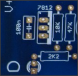
After that there should be 12V on the bottom pin. Else, the 7812 is faulty. Its metal tab must face to the right BTW.
I am getting 22VDC on the left pin (facing the front ) and no voltage on either of the other pins. I think the unit might be bad.. I just ran some wires and nothing changed.
Does 22VDC sounds right for the left pin? and it should be 12V output?
Does 22VDC sounds right for the left pin? and it should be 12V output?
If your transformer actually puts out about 17+17VAC on your mains then 22VDC sounds right, but sink the 7812 when you will replace it because 10V across gonna heat it up. The middle pin is grounding the chip so that via should give continuity to the general ground on the DMM. A good 7812 gives 12V on its right pin, that's its job.

Question on the Fets
I have the following fet spots open on the PCB:
two spots for K170
two spots for K1/0
One spot for C560
One spot for C550
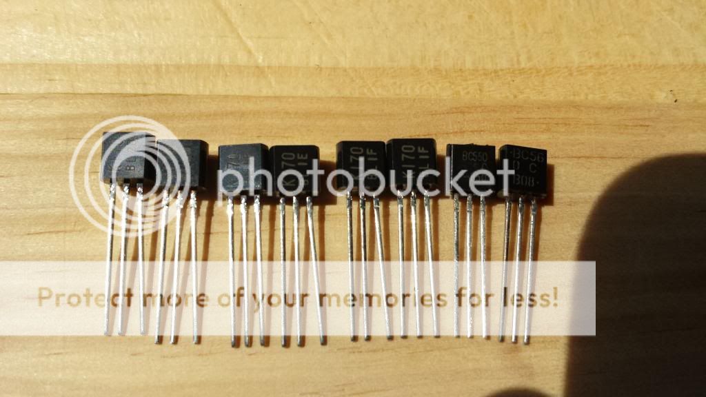
I have Tea Bags kit and have:
qty two - K170 BL20
qty two - K170 BL1E
qty two - K170 BL1F
Qty one - BC550
Qty one - BC56
I am not totally sure what I put where and I'm looking for help... Thanks all!
PS Photo of the fets from Tea Bag:
I have the following fet spots open on the PCB:
two spots for K170
two spots for K1/0
One spot for C560
One spot for C550
I have Tea Bags kit and have:
qty two - K170 BL20
qty two - K170 BL1E
qty two - K170 BL1F
Qty one - BC550
Qty one - BC56
I am not totally sure what I put where and I'm looking for help... Thanks all!
PS Photo of the fets from Tea Bag:
Last edited:
Correction on my Question on the Fets
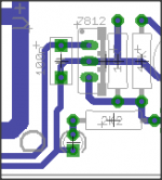
I have the following fet spots open on the PCB:
Four spots for K170
two spots for K1/0
One spot for C560
One spot for C550
I have Tea Bags kit and have:
qty two - K170 BL20
qty two - K170 BL1E
qty two - K170 BL1F
Qty one - BC550
Qty one - BC56
I am not totally sure what I put where and I'm looking for help... Thanks all!
There are matched pairs of 170's for the front in foil, the rest don't matter, place them in the power supply section. 2SK170BL is the type, the rest must be manufacturing info.
I have the matched pairs installed and saw how you matched them. Nice! You had a red sticker on the foil and they were a nice close match.
So I have a total of six K170. Do these go in the four spots marked K170 and the two spots marked K1/0 on the PCB?
Does the one marked BC56 go into the spot marked C560 on the PCB?
So I have a total of six K170. Do these go in the four spots marked K170 and the two spots marked K1/0 on the PCB?
Does the one marked BC56 go into the spot marked C560 on the PCB?
"BC56" is a BC560 (notice the "0" on the second line). There are no "2sk1/0", you are misreading the silkscreen. See the schematic.
Thanks for the help Teabag, nezbleu and henryve. I've built some stuff from kits etc and I'm pretty new to this. Lets just say I've worked the solder iron and had a part in the wrong spot before. what a pain!
I fixed my previous problem, I had a blown 7812.. One of the rectifiers had a cold solder and I guess some AC passed through to 7812. Fixed both, now everything is in spec.
Question.. Is it ok that +Vout and -Vout are +10.14/-10.14? I read that one needs to be higher than the other or something??
Also, should I use a CL-60 thermistor to connect ground to safety earth like in the F5?? I plan to bolt safety earth (from IEC) straight to chassis. How should I ground my RCA jacks? This is my primary area of concern.. And do I ground the board?
I see the IN/OUT molex have ground pins.. So should the grounds from each pair of RCA jacks go to the ground pin on the molex?
- Home
- Source & Line
- Analog Line Level
- Salas hotrodded blue DCB1 build