Re. Salas Q1 MJE15031 PNP TO-220 transistor on sink.
Yes, I got the 1531 on the Q1 slot, just typo error. So its a matter of getting a new DMM with a diode mode before any further testing. Thanks
Yes, I got the 1531 on the Q1 slot, just typo error. So its a matter of getting a new DMM with a diode mode before any further testing. Thanks
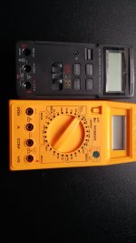
The yellow one surely has diode mode. Its the switch position next to hfe. Is it a Korean Metex?
No, all diode mode tests on transistors you do them when unpowered.Power on?
Regards,
Tom
My first digital display meter was a Metex. Different model but I recognized the general shape. About new one if needed see Brymen.
94mV is fishy. Because it could also be due to an interaction with another part, compare same test on the same transistor in your other fully working board.
The fully working board: pin2=460, pin 3=94
I went back to the non-working board: pin2=460, pin3=94, exactly the same as the working one, I must have read the wrong thing first time. so I guess its not the Q1.
I went back to the non-working board: pin2=460, pin3=94, exactly the same as the working one, I must have read the wrong thing first time. so I guess its not the Q1.
Based on the video Yurik posted test all transistors and JFETs vs the good board (positive voltage sections) to see if you may chance on something odd.
OK, will do that , but do I have to do the 10 segment LED? I have no idea how to do it, plus it lights up at the moment.
I got the measurement for the transistors. The figures were triple checked.
For the working board : Q2 bc550 B to E=545, B to C=199 /// J1 pf5102 G to S=032, G to D=102
For the non working board: Q2 bc550 B to E=541, B to C=102 /// J1 pf5102 G to S=009, G to D=009, smoking gun?
I also recheck mje15031 it should read 550/552 pin2 & 94 pin3. on both board. I was able to get a better contact this time.
On the -side of the non-working board, J2 was measured as G to S = 032, G to D =106, almost the same number as the working board.
I guess I have to order a new 5102 from Tea, yes?
I will connect the working DCSTB board (in mono) to the DCG3 just to test it out, and if I need more replacement parts I can order it from Tea all at the same time.
You may also try the JFET RDS resistance alternative test method shown in the video just to double check J1.
Hi!
Alas, I’m still not there!
Measurements (as posted a week ago) suggest a working DCG3, but there’s no sound at all (neither line out nor HP out).
Hopefully yet another silly glitch.
Will check the stage without VC, as well as the VC connected to i-select, as I suspect the bug could be there.
More to come.
- Home
- Source & Line
- Analog Line Level
- Salas DCG3 preamp (line & headphone)