A fully modern preamp system configuration. Congratulations. What attenuator impedance you calibrated for via the microcontroller? You will be probably discovering even more about sonic traits after familiar. Keep us posted.
Thanks!
I calibrated the attenuator impedance as 12K and the load impedance as 330K. I will try some NSL-32SR3 LDR's which have higher resistance/lower THD in a couple of weeks.
The preamp is mainly driven by a Soekris DAC (raw R2R signal, Rout=600R)
BTW; DC offset is max. 1mV
Try see how it compares to your now setting. Because this more than doubling in attenuator's impedance affects the bandwidth there should be some signs of bit different sonic presentation. Let us know what setting you preferred if you will think you could hear some differences indeed. If its worthwhile audible in your system you could try an intermediate point like 24k also for yet another comparison.
My offset measurements were with the op-amp in place.
After the device running for about 45 min with the lid on the temps were 50 C on the DCG3 sink and 57 C on the PS sinks (the middle ones). I think I'm going to change the R10s to 10 ohm, since it seems to be giving around 130 mA bias with other users (Asanden). That should be plenty I think.
What size are your heat sinks and does the case have any ventilation holes? Thanks.
1) Either solution will work. First one will look nicer, second one you can hand pick individual Leds for Vf if symmetry must be spot on in your application. In the first you can still vary the currents with R1 R2 to effect Vf total or add voltage with RxJ RyJ so to trim.
2) 5V Vin-Vout with such circuits is good to have across. Not that they won't work with less but for better performance. When using Schottky diodes you will be near there with 24VAC though. The mains stay usually higher than nominal also.
Okay, so I need to have at least 5V more going in or at least 17V for a 12V output?
If so, I would just use a 36V CT transformer.
Because I don't really understand how this PS works, I'm not clear on what you mean by "varying the currents with R1 and R2" if I short out some of the Kingbrights. 😕
Will raising their value from 33 ohms lower the output voltages or would I need to lower their values to get lower voltage?
Can a 100 ohm trimmer be substituted for R1 and R2 to vary the output voltages?
Thanks!
What size are your heat sinks and does the case have any ventilation holes? Thanks.
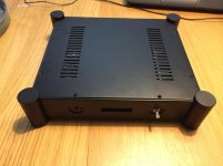
The sink is like this and the case is from eBay. You can see the ventilation holes on the top cover in my earlier post here. I have also drilled some additional ventilation holes between the sink's fins, as you can see in this post. I guess you could always have better ventilation, but this is the best I could do with my limited metal machining tools.
Edit: I added a couple of photos to clarify my enclosure.
Attachments

Last edited:
My offset measurements were with the op-amp in place.
After the device running for about 45 min with the lid on the temps were 50 C on the DCG3 sink and 57 C on the PS sinks (the middle ones). I think I'm going to change the R10s to 10 ohm, since it seems to be giving around 130 mA bias with other users (Asanden). That should be plenty I think.
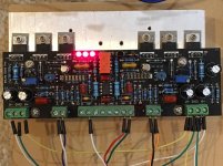
Now that I changed the R10s to 10 ohm my bias is running at 136/137 mA in L/R channels. The temperatures were after about 45 min with top cover on 46 C for DCG3 and 50 C for DCSTB middle sinks. I'm satisfied. Let's see when I find the time to complete wirings and get to finally listen to this beast.

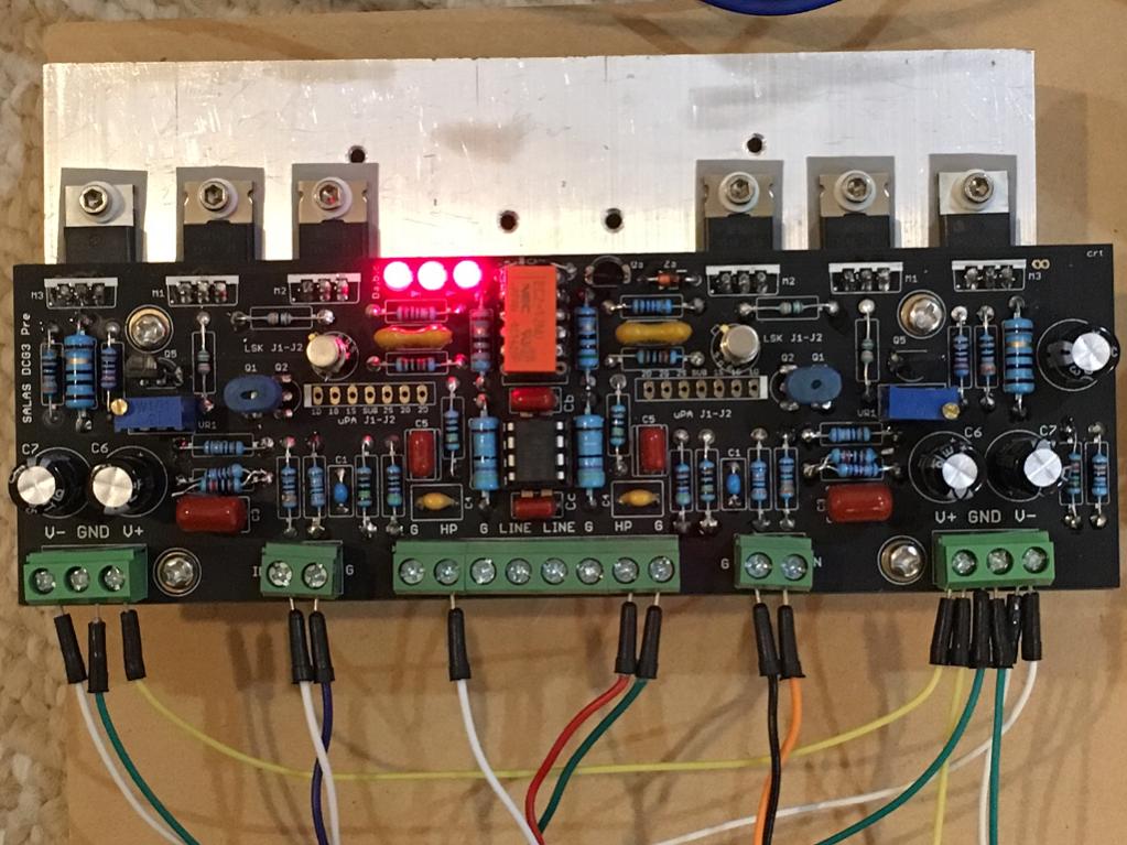
I just finished my DCG3 (Teabag board) tonight. The build was very smooth and it fired up the first time with 100mA bias. I had to adjust DC offset from 500mV down to 0mV. Then installed servo opamp. Listening to a few test tracks right now - very powerful headamp. I am using the shunt regulated PSU board from Prasi's HA project. Teabag's board is a pleasure to assemble - went together in less than 3 hrs and works the first time. I am using Idss matched DN2540's and Vgs matched IRF69610's, and Hfe matched BC560's. The LSK389's are from Linear Systems direct, and have been sitting in my bin of parts for 3 years and finally have a home here.
Amps sounds very nice. Thank you Salas and Teabag. 🙂
Amps sounds very nice. Thank you Salas and Teabag. 🙂
Attachments
Last edited:
Hi X. Nice to see your build. Metal can Jfets utilized too. Cool. What headphone you use?
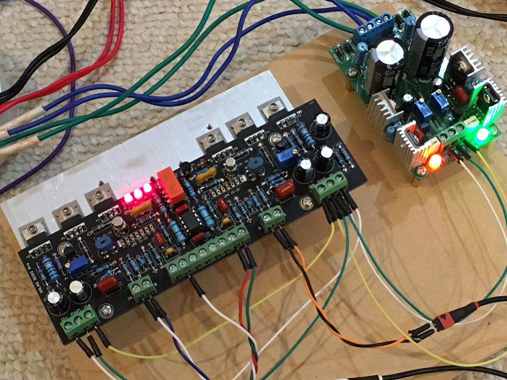
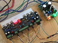
*That PSU has high output Z (as much as its noise cleaner section series resistor). Its a series chip regulated type with just a shunt noise cleaner. Otherwise it would have big sinks. Good for low noise but not to be sharing highly current swinging channels. I advise for either two of them or a low Z type, still better if two. Thick & short power rails cables use anyway also. There will be DC voltage loss too both on that PSU's series input and output resistors as well as on the long thin cabling. All those advised measures will be improving on slam, instruments differentiation, and resolution.
*That PSU has high output Z (as much as its noise cleaner section series resistor). Its a series chip regulated type with just a shunt noise cleaner. Otherwise it would have big sinks. Good for low noise but not to be sharing highly current swinging channels. I advise for either two of them or a low Z type, still better if two. Thick & short power rails cables use anyway also. There will be DC voltage loss too both on that PSU's series input and output resistors as well as on the long thin cabling. All those advised measures will be improving on slam, instruments differentiation, and resolution.
Now that I changed the R10s to 10 ohm my bias is running at 136/137 mA in L/R channels. The temperatures were after about 45 min with top cover on 46 C for DCG3 and 50 C for DCSTB middle sinks. I'm satisfied. Let's see when I find the time to complete wirings and get to finally listen to this beast.
Good compromise solution for the metal hardware involved. That's not low bias, its plenty. No worries 🙂
Okay, so I need to have at least 5V more going in or at least 17V for a 12V output?
If so, I would just use a 36V CT transformer.
Because I don't really understand how this PS works, I'm not clear on what you mean by "varying the currents with R1 and R2" if I short out some of the Kingbrights. 😕
Will raising their value from 33 ohms lower the output voltages or would I need to lower their values to get lower voltage?
Can a 100 ohm trimmer be substituted for R1 and R2 to vary the output voltages?
Thanks!
R1 & R2 govern the Id of the PF5102s by degenerating them. Those Id can differentiate the Vf of the Leds they feed constant current to. So its a place to can potentially trim out small Vref differences between the led bars. Rx Ry can cover easily when needing more V for a weaker rail to match a stronger one. Just additive correction though, can't trim down if you must.
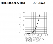
So yes, more degenerative resistor value is less voltage and less is more but don't expect large differences more than a useful matching range. See the Cf/Vf from the datasheet.
Can use trimmers but better replace with steady resistors after finding the values. For better noise & reliability.
24VCT is near enough and it will not give much heat to the pass transistors. 26VCT would be ideal. Not any transfo spec we like is ready made listed though. But its not a make or break goal to have >5V raw. Use Schottky rectifying diodes to save 0.7V of bridge drop.
Attachments
That PSU was just what I had lying around to test. Let me give it my real power supply with 100w 20v trafo and cap Mx and 20mF low ESR cap bank (20v rails) and see if slam improves. I have DT880-250's.
Here is what I should try it with (just replace the two amps on the CPU heatsinks):
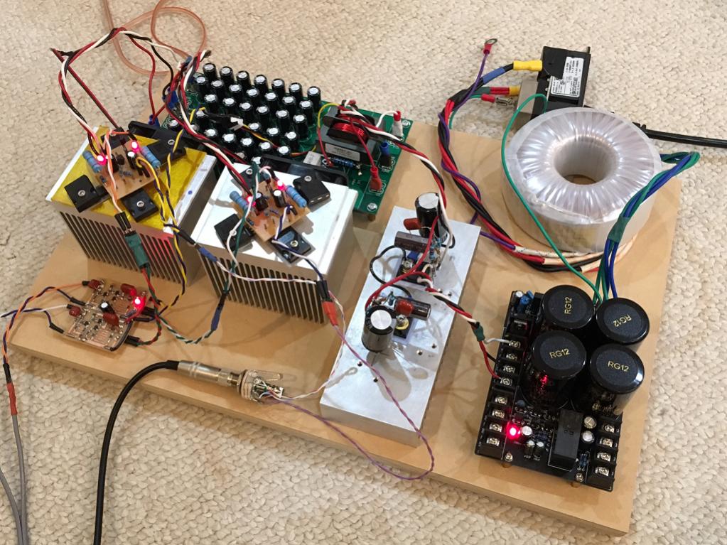
Here is what I should try it with (just replace the two amps on the CPU heatsinks):
20V rails will be knocking out the AD823 unless you have an OPA2604 to replace it that has up to +/-24V rails spec. It will be getting hot also because it uses more mA bias than most chips. Sound will change from your now 14V to 20V and the use of OPA to more upfront due to various reasons including the OPS stage behavior. Suitable to the rather sweeter HF kind of headphone like the HD 650 or the Audeze LCD2. But you will see for yourself. Let us know your configs and liking.
Should be less dangerous. Still, remove the AD823 and check the rails at the preamp's connectors to know where the PSU settles loaded before inserting the chip. If still more than +/-18V maybe a 5532 as a Sunday solution if having any. It has +/- 22V max spec. I remember it gave more mV offset because BJT input tech but also bit soft sonic subjectively so not too bad for Beyer. Maybe make R14 more aggressive value i.e. lower if you will find the offset control too loose with a 5532.
BTW a recording style that becomes the 770 80s is like this one I am listening on right now: https://www.youtube.com/watch?v=qG1U2KRn0RU
Your 880s have less artificial bass oomph because semi open but more linear. Try it though.
Your 880s have less artificial bass oomph because semi open but more linear. Try it though.
Thanks for the song - very nice. I also like this one for testing head phone amps.
https://www.youtube.com/watch?v=s6_B1AB9nu8&sns=em
https://www.youtube.com/watch?v=s6_B1AB9nu8&sns=em
BTW a recording style that becomes the 770 80s is like this one I am listening on right now: https://www.youtube.com/watch?v=qG1U2KRn0RU
Your 880s have less artificial bass oomph because semi open but more linear. Try it though.
Talk about a small world. They started out in Germantown, Maryland, just north of me.
They had played in Athens GR a couple of times also. Have seen them live in summer 2014. They had great crowd support, a large mass of bearded fans moving like huge sea waves. Especially when they performed The Regulator there was an eerie almost full crowd strong chanting along.
- Home
- Source & Line
- Analog Line Level
- Salas DCG3 preamp (line & headphone)