Yes AC primary fuse. I have a single one which leads to the 2 primaries. 230V/50Hz in Singspore.
Use 2Α slow blow (T type) as common primary fuse for your two 80VA transformers. To can stand their current surges at power on due to instantaneous magnetic build up.
Yeah. I did not find anything short, esp. checking the metal tabs for continuity.
Your 900 type SilPads as seen in #3212 are better for TO-247 size cases so they offer some play to TO-220 mounting. If in combination with largish mounting holes drilled to the chassis they can set traps of unseen continuity. Thus rechecking all the MOSFET tabs to chassis insulation with the Ohm meter is a good thing you did for peace of mind.
P.S. If you will not find any short, the explanation could be that the fuse wire was getting too hot so it weakened and snapped from the drilling vibration.
Seems like this is the explanation - i have replaced with a 1A25 fuse which I found in the box and all is well again 😀
Yeah, but who needs low Zout.....😀Its a nice series supply if you need cut on dissipation and have dual mono. Can also be configured for different Vout with some modding. Good to have in your arsenal. The UltraBiB has much lower Zout of course.
I learnt from listening and also from extensive spice modelling, that stage decoupling really can bring out the very best of a given design. Low Zout of the PS does help in this respect.
Now that the UBiB already does provide two positive regulators, why not take another step forward and use one of them to exclusively feed the input stage current mirror and the other one for all the rest?
Anybody already tried?
Last edited:
Possibly rising the voltage of the first stage will also add some benefits for operating the BC327-40 in an even more linear range. Just a wild guess at the moment, though.
I already ordered a second transformer pair to be prepaired. 🙂
I already ordered a second transformer pair to be prepaired. 🙂
Last edited:
To do different stages rails you would need to hack the board with a hobby knife. Watch J3's max VDS though.
DCG3 boards V1.04 possibly upcoming?
🙂
But why J3? Only (mostly) the positive rail of the first stage is interesting to be modified IMO, because the neg rail is loaded by current sources only, so not much stage coupling going on there.
Would you consider doubling the positive voltage is a good starting point?
🙂
But why J3? Only (mostly) the positive rail of the first stage is interesting to be modified IMO, because the neg rail is loaded by current sources only, so not much stage coupling going on there.
Would you consider doubling the positive voltage is a good starting point?
Last edited:
In case you had in mind to up symmetrically. Remember that you must protect the op-amp and relay by keeping the standard level of voltages to them.
P.S. Yes I had already sent the V1.03 details to Tea a couple of weeks ago or so. It should be feasible to have them on next run, unless he wants to do a test assembly first to be safe than sorry and he wouldn't make it in time.
No not exactly.In case you had in mind to up symmetrically.
The idea was to make use of the until now unused second positive regulator of the UlraBiB board.
As the first stage of the DCG3 already has proven to be a delicate spot, my conclusion was, that isolating this stage should result in even better performance.
First stage always is a fragile spot for unintentional interstage coupling through the rail, as there it is that the loop gets closed, the gain is high and signals are small.
In other words, PSRR of this stage usually is quite lowish. This easily should show up in SPICE modelling too.
Just feeding the current mirror with its own voltage should not affect any of the other stages. Those will be fed exactly as before. Am I any wrong here?
Last edited:
Even a simple RC filter front up to the current mirror my have some positive effect, I think.
Seen this in other designs and it worked quite well, at least when the cap was wired straight to the star mass point.
The downside of this approach is, that PSRR and thus interstage isolation, gets less and less as frequency drops.
Seen this in other designs and it worked quite well, at least when the cap was wired straight to the star mass point.
The downside of this approach is, that PSRR and thus interstage isolation, gets less and less as frequency drops.
Last edited:
It has at least 40dB 1kHz to 20kHz PSRR as a whole when I tested for it through speaker coil VDC feed and capacitor to gen which is the practical limit of my 8 bit DSO. Simulation is indicative but it does not know layout so take it with a pinch of salt if producing some very good PSRR figure. Sometimes there can be odd results when breaking the rail of a tightly knit system and I did not see need for it by the IMD SMPTE 250Hz 8kHz 4:1 measurement so its up to your curiosity to try and see. There is very steady Class A bias in the output stage (not only using CCS but its set in the Mosfets zero tempco region also). So small signals don't rock the boat but if you have in mind difficult to drive headphones you may achieve something bit better for when listening loud is my best guess. On the other hand, more output stage current bias could possibly achieve somewhat analogous goodness in that occasion as well.
From my post #17
"Here is IMD SMPTE when driving 120 Ohm for instance. That's strong 250Hz trying to modulate quieter 8kHZ. See the little bass tone modulations around the high tone's base. 0.0027% modulation at 101dB SPL with those AKG. Means clarity in busy music. Not easy to do that with SE tube headphone amp."
"Here is IMD SMPTE when driving 120 Ohm for instance. That's strong 250Hz trying to modulate quieter 8kHZ. See the little bass tone modulations around the high tone's base. 0.0027% modulation at 101dB SPL with those AKG. Means clarity in busy music. Not easy to do that with SE tube headphone amp."
Attachments
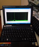
P.S. The load on the above test was specifically the AKG K612 PRO medium sensitivity headphone which has a reputation of being difficult to really move. And it is. Significantly quieter with "meh" quality than the HD600 on my PC's direct output, but on the DCG3 its flying.
thanks
But don't hold your breath until you get results from this setup. My speed in bringing projects to a end is really slow.
First attempt with the amp of yours is back almost 2 years now, with all the parts laying around since, but there has been a rather lengthy detour with STAX gear that in the end I got not happy with.
Have thrown in my ideas as my interest in your amp has come back more recently. A result of my anticlimatic experience with ES headphones.
Headphones to drive with the DCG3 for now will be my proven and matured AKG K701 and/ or a K712 PRO I was lucky to get pretty cheap and which will arrive these days.
The K712 will be modded to full symmetric with a 4pin mini XLR plug.
Last edited:
K712 PRO is nice. I had listened to it on the DCG3 as the K701 also. Bit more opaque than HD6xx but full & musical, light to wear, tonally much better than the K701 more natural but not as scrutinizing or wide, and at half the price than the cleaner and wider than HD600 but arguably grittier HD660S.
Was indecisive about the K712 PRO ya know.
But as I would have liked to test its special memory foam pads on the K701 anyway which is said that they up the lower register of the K701 by improved acoustic isolation and as those pads are about EUR 100,- a set I had to find out, the price for a complete K712 all of a sudden dropped by this EUR 100,- 😀
But as I would have liked to test its special memory foam pads on the K701 anyway which is said that they up the lower register of the K701 by improved acoustic isolation and as those pads are about EUR 100,- a set I had to find out, the price for a complete K712 all of a sudden dropped by this EUR 100,- 😀
Last edited:
I'm building another one to test a balanced setup and to do an immediate A-B comparison with different components, so I'm fine tuning things
While I measure almost the same draw from negative and positive side I do remember that it is recommended to have more current available for positive side. Of course this is of no concern for linear psu or DCSTB but it is for shunt one like UBIB
Is this because the positive side, although drawing same current, have bigger swing ?
If so, could the following shunt (extra) current setup be OK
shunt current for UBIB
normal
positive 100mA
negative 50mA
hotrodded
positive 200mA
negative 150mA
Both rails draw 100mA when idle in conservative bias mode. Positive can draw up to 200mA pk. In other words twice its idle, what idle you opted for. Negative draw stays virtually static at 100mA or other mA bias choice, its a CCS. Thus 200mA peak current drive is available to the load before asymmetrical clip in the conservative bias example. Depending on your worst anticipated type of load and its pk, allow 100mA spare current above rails draw for each polarity's UltraBiB.
- Home
- Source & Line
- Analog Line Level
- Salas DCG3 preamp (line & headphone)