I personally follow the VituixCAD guidelines of measuring each driver's on it's own axis and entering y-offset. But I've seen many people measure on the tweeter axis and then keep the offsets zero.That is wrong - in VituixCAD all driver measurement must be taken at their own axis!
...
Unfortunately, no. That is not how VituixCAD expects to see measured data.
I'm pretty sure it only makes a minor difference and its okay the way he has it. Hopefully someone who knows for sure can chime in.

The measurements on the tweeter than mid were taken at 670mm while the woofer measurment was taken at 380mm. I decided to follow the vituix guide this time and dropped the mic for the woofer measurment.
The tweeter and mid were taken right in the mid of each other per the guide at 670mm height from base of cabinet. The woofer was taken at it own height of 380mmYes!
Oh no! It didn't occur to me as a possibility! That is wrong - in VituixCAD all driver measurement must be taken at their own axis!
@Bmsluite ? How did you measure the drivers, on which axis?
Unfortunately, no. That is not how VituixCAD expects to see measured data.
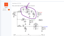
Forgot to tell you i switched it up. Tweeter and mid taken at 675 and woofer taken at 380mmx, y, and z offset are in crossover section, not the drivers, lower left. See red circle in the attached image.
BUT...you measured all of your drivers on the tweeter's axis, not on thier own axes, correct? In that case, your y-offsets are zero...I think.
Or all measurements were taken on the tweeter axis...I think.
View attachment 1336141
Just another trick we use regularly in the shop here (paid projects): if you need a 30 watt 6 ohm resistor but that is expensive you can just use 3x 10 watt 2 ohm resistors inline. Same result. You'll probably want to use 1%ers here though as you have multiplied the off spec by 3 times using three of them. Higher wattage resistor can get expensiveI agree that it's not true in all cases, but I think it's a safer practice, especially for people who are new to crossovers. As I understand it, there's a lot of math with it that's way over my head. It's plenty safe with tweeters but I would be concerned with a resistor first in line with a mid range driver unless the resistor is at least 25 watts (prefer 50). But again, I can't do all of the math. I have, however, had a resistor burn my hand in a mid range circuit when I used it first in line. I've never had that problem when they're after the filters.
What is this thing? I haven't seen this form of filter before.Now, even lower woofer-mid frequency crossover:
View attachment 1336137
View attachment 1336138
View attachment 1336139
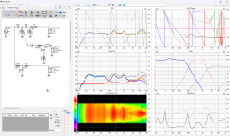
But there is a caveat: impedance between 70 Hz and 250 Hz is becoming dangerously low.
Important note: you don't have "Y" values - distances between drivers! Crossover above would be correct ONLY IF the drivers are coaxial design! Please post distances between drivers!
Attachments
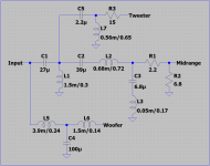
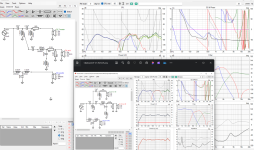
I will try entering this in but I think that tweeter is gonna distort at higher wattages since its leaking really low into the frequency bandWhile the measurement offsets issue get sorted out, I thought I'd give it a go anyways even if further tweaking will be required, just to show an alternative topology. As I said before I don't have VituixCAD, I use an Excel spreadsheet I made myself, so I've drawn the schematic in LTSpice, see below.
I know L3 could be tweaked further to catch the midrange peak better but I've tried to use standard / easy to find component values. Note that I only considered the on-axis response and basically aimed at flatness where it matters most, good phase tracking at the crossover points and a reasonable impedance curve. Could be a good starting point for further tweaking. It would be nice if one of you VituixCAD users could kindly enter it there to see what it looks like.
Please note that I shifted all levels up by 40dB for better viewing in my spreadsheet, hence the average level ~100dB, and the scale is different from the VituixCAD plots, I show all the way down to 0 so I can plot impedance in the same graph. The tweeter is down by 50dB @ 1kHz, I think it will be ok.
270 nF plus 5.6 ohms together with 1 mH form notch filter at about 10 kHz, in order to clean midrange high output mess there.What is this thing? I haven't seen this form of filter before.
Edit: Further, 1 mH plus 8.2 uF form second order low-pass filter.
Comes in kinda wonkyWhile the measurement offsets issue get sorted out, I thought I'd give it a go anyways even if further tweaking will be required, just to show an alternative topology. As I said before I don't have VituixCAD, I use an Excel spreadsheet I made myself, so I've drawn the schematic in LTSpice, see below.
I know L3 could be tweaked further to catch the midrange peak better but I've tried to use standard / easy to find component values. Note that I only considered the on-axis response and basically aimed at flatness where it matters most, good phase tracking at the crossover points and a reasonable impedance curve. Could be a good starting point for further tweaking. It would be nice if one of you VituixCAD users could kindly enter it there to see what it looks like.
Attachments
ahhhhh ok I see it now270 nF plus 5.6 ohms together with 1 mH form notch filter at about 10 kHz, in order to clean midrange high output mess there.
A few values are wrong and you didn't include the L-pad for the mid driver, please double checkComes in kinda wonky
Attachments
To make it sure I understand you right: you measured both tweeter and mid (separately) at the same point/axis which is in the middle between the two? That is wrong! This is the correct procedure: measure at tweeter height, than drop the mike at the mid axis and then measure the mid, and on the end - drop the mike again at the woofer axis height and measure the woofer.The tweeter and mid were taken right in the mid of each other per the guide at 670mm height from base of cabinet. The woofer was taken at it own height of 380mm
Until you measure it again, we have to work with these "Y" values:
Ytweeter = 0
Ymid = 0
Ywoofer = 380-670 = -290 mm (or 380-675 = -295 mm). Which one is correct - 670 or 675 mm?
Last edited:
675.To make it sure I understand you right: you measured both tweeter and mid (separately) at the same point/axis which is in the middle between the two? That is wrong! This is the correct procedure: measure at tweeter height, than drop the mike at the mid axis and then measure the mid, and on the end - drop the mike again at the woofer axis height and measure the woofer.
Until you measure it again, we have to work with these "Y" values:
Ytweeter = 0
Ymid = 0
Ywoofer = 380-670 = -290 mm (or 380-675 = -295 mm). Which one is correct - 670 or 675 mm?
The guide literally said I could take it at the same height for both of them. I wanted to minimize me accidentally angling the mic between measurements
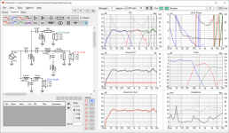
I see that, that's not good. These will be listened to 90% of the time at 15 degrees off axis. Any way to fix this or is it just the nature of the drivers at the distance I have them apart?With Ywoofer = -290 mm:
View attachment 1336377
Take note on the vertical directivity graphs (lower left diagram) - there is woofer-mid cancelation at 300 Hz.
View attachment 1336378
I'll your new one. Yeah, vituixcad is pretty easy to use. Understanding the tools is a little more challenging but worth learning I thinkA few values are wrong and you didn't include the L-pad for the mid driver, please double check
I think something isn't loaded right. Did you load all the on/off axis measurements into the driver tab? You can load all the different angled measurements in thereCorrected values
Edit: it's pretty intuitive, I may become a convert...
Attachments
I think I may have screwed up and given you guys some wrong files. I just ran through everybody's and none of them translate with the loaded measurements. I am going to move this XO into a new thread. I will post where that thread is in a minute.With Ywoofer = -290 mm:
View attachment 1336377
Take note on the vertical directivity graphs (lower left diagram) - there is woofer-mid cancelation at 300 Hz.
View attachment 1336378
I will make a new zip file with all the measurements and triple check that I have loaded up the right ones.
I apologize, I do very much appreciate the help I am being given and feel bad that I have wasted some of your time.
- Home
- Loudspeakers
- Multi-Way
- Saggy Bandpass filter