I have a modushop slimline case to use for an amp build & am a bit unsure about how best to safely ground the chassis.
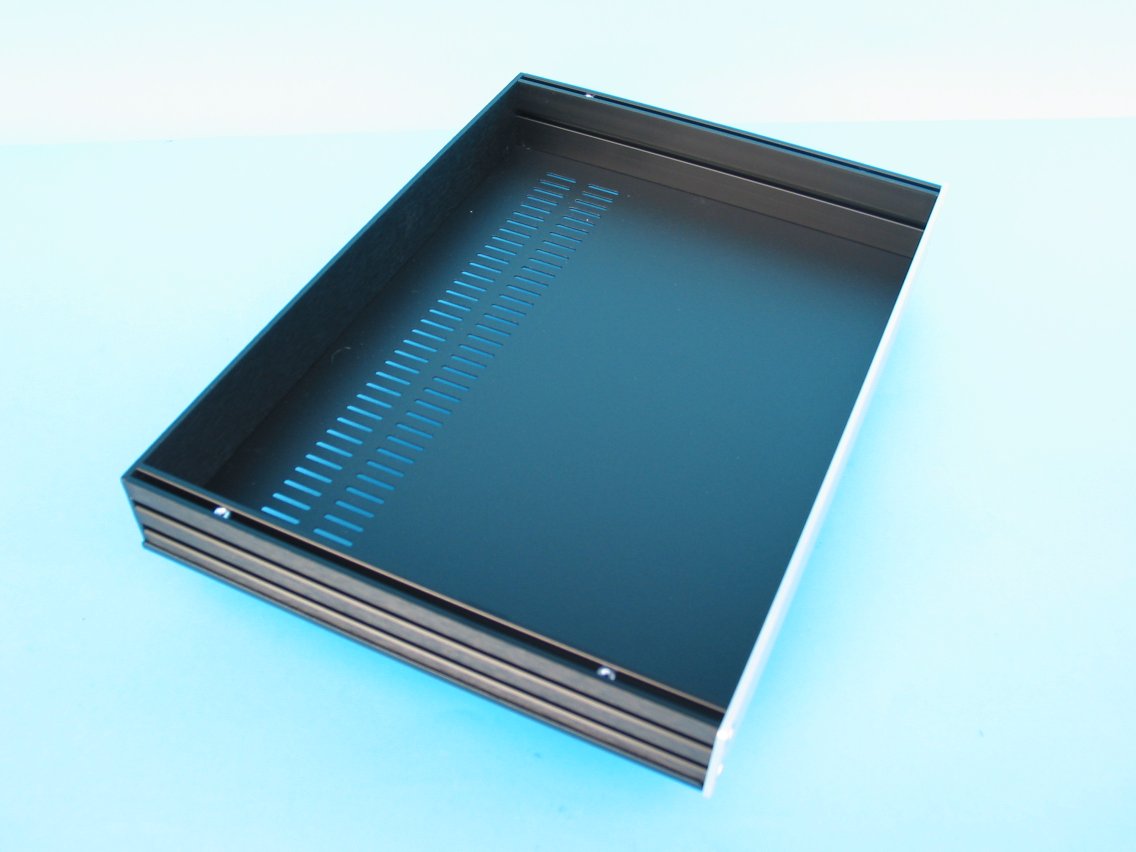
It is made from anodised aluminium panels on the sides/front/back and painted steel sheets for the top/bottom. These are joined together via a number of grooves in the side panels. If I put a ground lug into the base alone then I'm not confident the base panel is going to make a secure connection to all other panels even if I grind/sand away the covering where the panels meet.
Alternatives I've thought of include running additional cables from that ground lug to each panel or attaching some internal metal brackets to join adjacent panels.
Any recommendations/tips on how to deal with this would be much appreciated.
Some pics to illustrate
the grooved side panels:
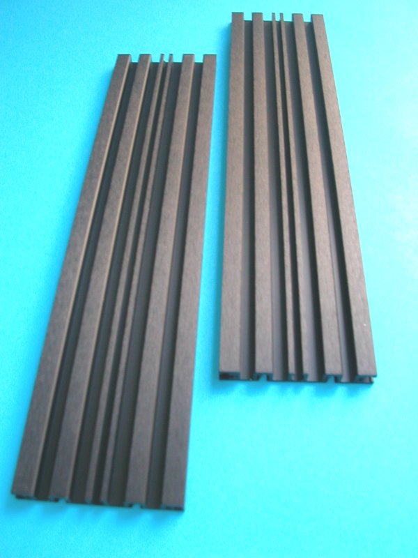
the top/bottom attach via a bolt slid into the 1st channel, panel is then screwed into that bolt
the front and back then attach via screws that are threaded into the next slot down, I think the panel is anodised after threading.
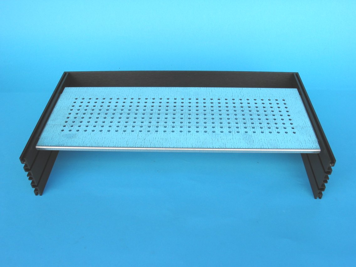
It is made from anodised aluminium panels on the sides/front/back and painted steel sheets for the top/bottom. These are joined together via a number of grooves in the side panels. If I put a ground lug into the base alone then I'm not confident the base panel is going to make a secure connection to all other panels even if I grind/sand away the covering where the panels meet.
Alternatives I've thought of include running additional cables from that ground lug to each panel or attaching some internal metal brackets to join adjacent panels.
Any recommendations/tips on how to deal with this would be much appreciated.
Some pics to illustrate
the grooved side panels:
the top/bottom attach via a bolt slid into the 1st channel, panel is then screwed into that bolt
the front and back then attach via screws that are threaded into the next slot down, I think the panel is anodised after threading.
Last edited:
It would be more important to ground the perimeter than the internal support plate. If you have rectifiers or something like that mounted to that plate, you can use those mount screws as a good place to jump from, to the perimeter chassis. You'll either have to do something extra to get yourself confident, or trust that the chassis will remain conductive to all sides. Personally, I would measure the resistance when assembled and then trust it. It may be possible to sandwich some crimp lug connectors between those joints in some way, but I wouldn't go to much extreme if everything measures well.
S
S
Daisy chain green ground wires on all parts of the chassis. Wire size should be large enough
to carry sufficient current to trip the breaker. Use a separate ground screw for the IEC outlet.
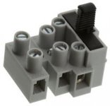
Good advice! I recently used 2 Galaxy cases of said manufacturer and after checking/measuring only the bottom plate made good contact with PE as I used a fused terminal Block (please use those as they already have their middle pin connected to chassis AND offer an extra PE connection for daisy chaining PE.
That was the first time I experienced a metal casing not to conduct as I like it. Please note that the casings themselves are good quality. No complaints but PE just demands attention. The way the upper and lower cover are mounted they do not conduct properly to the aluminium anodized side panels (at least with the Galaxy series but yours seems the same). It is caused by the construction using countersunk M3 screws on painted steel covers to “loose” M3 nuts that are shoved in an anodized aluminium extruded profile. The nuts don’t make good contact to the aluminium side panels.
Beware: fused terminal blocks have the middle connector connected to the mounting screw and thus PE. More than once I have seen people using this connection for either L or N which might give unwanted side effects. As simple as these devices are, as many misunderstanding they apparently create
")
Attachments
Last edited:
It is cursing in the church with english people but please lift PE with a 10 Ohm 5W resistor to the casing so you won’t have a ground loop. I am very aware that english speaking countries have the custom to connect audio GND straight to PE but that is detrimental for the final result.
Either connect all metal parts of the casing to PE and leave audio GND floating or use the 10 Ohm method. Both ways will result in troublefree humless and still safe audio.
 Correction
Member has requested the first paragraph be changed to:
Either connect all metal parts of the casing to PE and leave audio GND floating or use the 10 Ohm method. Both ways will result in troublefree humless and still safe audio.
CorrectionMember has requested the first paragraph be changed to:
please lift audio GND with a 10 Ohm 5W resistor to the casing (which is connected to PE) so you won’t have a ground loop.
Last edited:
You will see the 10r resistor providing the "lift". As a note, I use two lifts, one for analog from amplifier, and one from digital and smps.
This way the two worlds are separated by 20r between, centered on earth, and chassis ground earthed. You can separate your grounds.
S
This way the two worlds are separated by 20r between, centered on earth, and chassis ground earthed. You can separate your grounds.
S
I am not an experienced amp builder so this might be a Q with an obvious answer however I haven't found a concrete answer so I'll ask here
practically speaking, given a class i design and connectors which are made of metal (i.e. NC3FD-LX | Neutrik), how would one actually float audio ground? or is this basically saying "make it class ii" (because the entire audio circuit must be insulated from the chassis)?
practically speaking, given a class i design and connectors which are made of metal (i.e. NC3FD-LX | Neutrik), how would one actually float audio ground? or is this basically saying "make it class ii" (because the entire audio circuit must be insulated from the chassis)?
- Home
- Design & Build
- Construction Tips
- Safely grounding a modushop slimline chassis