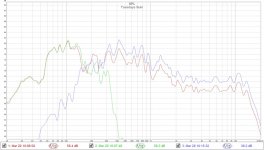
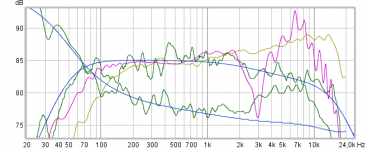
You really need to get the vertical graphs to have no more than 80 dB variation, preferably only 50dB from min to max and 10dB/major divsion. 5dB is even better. Please see axis limits on my graph and try to show using similar scale.
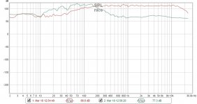
This is unreadable - as the variations are huge and covered up with lack of magnification in vertical scale:
It looks like it is improving but hard to tell and need all 3 curves laid on top in contrasting colors.
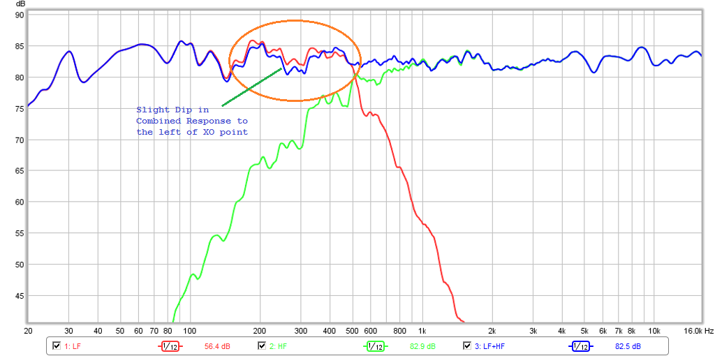
The tell-tale sign of a proper Harsch XO is the little wiggle in the bass where it actually dips a little below woofer only right to the left of the XO point, you may actually have that in yours but hard to tell at this scale:
The other tell, is a flat phase response with a slight rise of circa 60deg at the XO frequency.
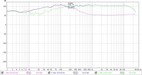
This is unreadable - as the variations are huge and covered up with lack of magnification in vertical scale:
It looks like it is improving but hard to tell and need all 3 curves laid on top in contrasting colors.
The tell-tale sign of a proper Harsch XO is the little wiggle in the bass where it actually dips a little below woofer only right to the left of the XO point, you may actually have that in yours but hard to tell at this scale:
The other tell, is a flat phase response with a slight rise of circa 60deg at the XO frequency.
Attachments

Last edited:
xrk971: I dont recall seeing a 60deg rise of the phase response at the XO point - Though I think I can get pretty nice (EPIC) stepresponse. - I think the phase is more or less flat around the XO. Why is this so?
mkane, take a break for a while and just listen to them, don't wanna lose you down that rabbit hole
Taking a break with my wife. Were headed to Molokai Wednesday for 10 days. I've made so many errors just getting the numbers in the right places along with the inputs connected to the right outputs, etc. haven't even explored Harsch x over yet. I'm at an HP BW2 @ 53 Hz right now.
Attachments
xrk971: I dont recall seeing a 60deg rise of the phase response at the XO point - Though I think I can get pretty nice (EPIC) stepresponse. - I think the phase is more or less flat around the XO. Why is this so?
Probably he is busy working on a new comparison thread : )
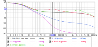
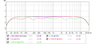
Can this help a 20Hz-20kHz minimum phase pass band verse @160Hz LR2 / LR4 / HARSCH and then a @2400Hz HARSCH as yours, cursor is positioned at 60º.
Phase domain:
Amplitude domain:
Attachments
Last edited:
.....mkane, take a break for a while and just listen to them, don't wanna lose you down that rabbit hole

Taking a break with my wife. Were headed to Molokai Wednesday for 10 days. I've made so many errors just getting the numbers in the right places along with the inputs connected to the right outputs, etc. haven't even explored Harsch x over yet. I'm at an HP BW2 @ 53 Hz right now.
Can be a very big mouthful starting from scratch use modern DSP control and all its possibilities so think take your time there mkane77g and maybe ten nice days with wife and Molokai will help 🙂
Actual had below slopes at a time and just needed their SPL balanced right plus set the right delay for mid-tweeter, but then something advanced or strange happened with number settings and routing in miniDSP plus cable mismatch and the set back is obvious visible in makane77g latest post 567.
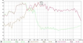
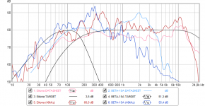
Note pass bands are real measurements emailed between countries where sum is a synthetic REW math:
For interested about planning (see legends) here is how it looks for datasheet curves verse mkane77g's in situation raw SLOB system:
Any skeptic view or critics is of course welcome such as for example we have reflections into our slopes and that target is not a good house curve etc, but as i see it lets first get some positive results in that microphone position so we know mkane77g is able to dial all the right switches, after that will look into the more complicated analysis and see if its possible educate makane77g why acoustic waves verse electric domain is so nervous a domain to base right corrections.
Attachments
Last edited:
xrk971: I dont recall seeing a 60deg rise of the phase response at the XO point - Though I think I can get pretty nice (EPIC) stepresponse. - I think the phase is more or less flat around the XO. Why is this so?
I think Byrtt shows a nice example. In Post #1, Harsch's own paper shows a 60 deg bump at the XO:
Why? That is just a fallout of the math I suppose (a BW4 and BES2 with the Harsch specified delay). The result is quasi-transient perfect - not quite transient perfect, in which case it would be flat throughout the XO region.
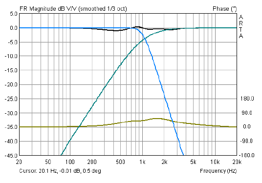
My 10F/RS225 with passive transient perfect 1st order XO is indeed flat through the XO region:
XO is around 600Hz to 900Hz, or thereabouts.
...The result is quasi-transient perfect - not quite transient perfect, in which case it would be flat throughout the XO region...
Agree solution involve compromise as often is case in speaker building.
...My 10F/RS225 with passive transient perfect 1st order XO is indeed flat through the XO region...
Indeed its not flat through the XO region 😉 can we look at it one more time ...

The so called passive transient perfect 10F/RS225 ref. monitor have slopes that are not very smooth and precise dialed in and you will see it ask REW "generate minimum phase" for that particular amplitude response shared, below is a synthetic compare for that amplitude response and how it should look benchmarked in a 48kHz measurement chain, phase errors above 2kHz is not flat and looks more than a 50º textbook deviation:
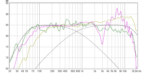
Overlaid with target curves @750Hz and manufactures datasheet response its not hard to see why it gets a falling response as frq goes up, 10F native response up there should have ruled that area but RS225 mark its signature above 2kHz area:
Also BW1 involve compromises one of them is XO region is huge so will need very smooth and wide band drivers and still if drivers are dialed in with beautiful smooth slopes then if one move microphone a bit up or down funny ripple schemes show up, and think it say itself because XO area is so wide and always out of phase except in one specific vertical microphone position, now use BW1 slopes for a coxial driver where center to center distance is zero and we can talk a theoretic perfect minimum phase system sum.
Attachments

Hi xrk971,Hi Byrtt,
I meant flat as in relatively flat within +/-25 deg from 100Hz to 10kHz:
😉 how should we know what you meant without tell us, but argument doesn't change much look at it again on that design axis its not flat within +/- 25º at all because the textbook phase for that amplitude response should at 10kHz point be down at about -21º and about 1kHz point phase should cross zero deg so phase above 1kHz point is all in negative direction numbers when measurement chain is running 48kHz, REW will tell about the right phase trace belonging that amplitude if you mind push "Generate minimum phase". With your insight i don't get why state details that in theory 1st order XO is transient perfect and Harsch is not quite transient perfect without at least show build is performing relative within target specs, and to get there with a 1st order XO slope it will probably need massive more correction, furthermore also related your insight to speaker building then how that diy speaker with its current state 1st order slope configuration have come to consumer market as a "Transient Perfect FAST Speaker" €2000 product is more than surprising without inform anything more about pros and cons.
Hi Byrtt,
I am not sure if there is any disagreement between what I said, and what you are saying?
And I said it is within a tolerance band of +/-25deg which seems consistent with being off by 21deg at 1kHz, and despite whether or not the phase is going up or down, it is relatively flat in the main telephone band (600Hz to 6kHz) where spatial cues are derived. Maybe you are picking at the term transient *perfect*, because of course, no driver is perfectly wide bandwidth from DC to infinity. I think what I am refering to is how different the phase is compared to say a LR2 type speaker where it actually wraps over 360deg.
It's also interesting that this was the same XO and basic speaker that you helped me to develop back in the 10F/RS225 thread:
http://www.diyaudio.com/forums/full...-rs225-8-fast-ref-monitor-16.html#post4328022
Back then, you were not saying anything about all the issues you seem to be finding with it now?
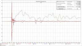
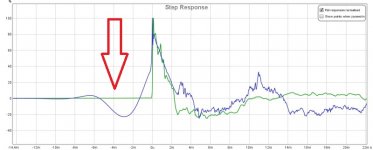
But despite any questions about how flat the phase is, if we look at the step response, it exhibits the classic features of the right triangle shape of the transient perfect speaker. Yes, I know this is at the location of the mic and you will say that at other positions it won't be the same because it not coaxial. However, the error is minimal due to the cos(theta) effect at small angles farther away, the effect diminishes quickly as cos(0)=1.

Alas, we are getting off topic as this is the Harsch XO thread, and not the BW1 XO thread 🙂
I am not sure if there is any disagreement between what I said, and what you are saying?
the textbook phase for that amplitude response should at 10kHz point be down at about -21º and about 1kHz point phase should cross zero deg so phase above 1kHz point is all in negative direction
And I said it is within a tolerance band of +/-25deg which seems consistent with being off by 21deg at 1kHz, and despite whether or not the phase is going up or down, it is relatively flat in the main telephone band (600Hz to 6kHz) where spatial cues are derived. Maybe you are picking at the term transient *perfect*, because of course, no driver is perfectly wide bandwidth from DC to infinity. I think what I am refering to is how different the phase is compared to say a LR2 type speaker where it actually wraps over 360deg.
It's also interesting that this was the same XO and basic speaker that you helped me to develop back in the 10F/RS225 thread:
http://www.diyaudio.com/forums/full...-rs225-8-fast-ref-monitor-16.html#post4328022
Back then, you were not saying anything about all the issues you seem to be finding with it now?
But despite any questions about how flat the phase is, if we look at the step response, it exhibits the classic features of the right triangle shape of the transient perfect speaker. Yes, I know this is at the location of the mic and you will say that at other positions it won't be the same because it not coaxial. However, the error is minimal due to the cos(theta) effect at small angles farther away, the effect diminishes quickly as cos(0)=1.
Alas, we are getting off topic as this is the Harsch XO thread, and not the BW1 XO thread 🙂
Last edited:
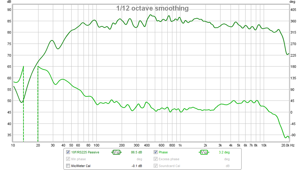
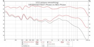
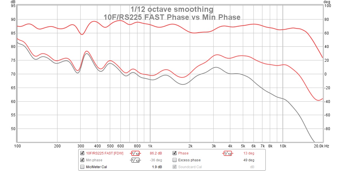
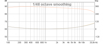
So I just pulled out the microphone and took this data hot off the press, selected 6-cycles FDW and clicked generate minimum phase. You can see it crosses through zero at 1kHz as you say, and is exactly 50deg variance between actual phase and minimum phase at 10kHz. No need to generate any synthetic FR's, this is the actual speaker measured minutes ago.

Attachments
Last edited:
So I just pulled out the microphone and took this data hot off the press, selected 6-cycles FDW and clicked generate minimum phase. You can see it crosses through zero at 1kHz as you say, and is exactly 50deg variance between actual phase and minimum phase at 10kHz. No need to generate any synthetic FR's, this is the actual speaker measured minutes ago.
Thanks above data X, i'm sorry it looks you misunderstand how to read absolute verse the minimum phase curve, for a filtered and good enough measurements those two starts be the same when design is transient perfect and on a design axis can be brought to overlay each other so if excess phase is ticked on it will show a flat strait line, in above distortion looks start at about 600hz area and up where absolute phase starts deviate more and more from minimum phase domain for what it should have looked liked for the measured amplitude response, if it can help then for example a two way speaker with 1kHz LR4 XO having a same amplitude response as above would have generated exactly same minimum phase trace but the absolute phase would rotate 360º more excess phase around 1kHz point.
June 2017 acoustic design axis 10F in FAST transient perfect band pass 1/6 FDW, absolute phase verse minimum phase:
Look for case I'm in reality not after you as you probably think and hope critics will sink in as constructional and friendly, for the first you started up here trying to show superiority to Harsh excess phase distortion using another example full of excess phase distortion, for the second you did know from that other build thread myself have big trouble accept claimed sky-high performance when speaker is setup with suchs a simple passive XO network covering so wide a region including a alu cone woofer, and also because yes i could see my mother sure in her case go all out buy this speaker because its marketing says nothing but its a transient perfect reference monitor.
I can't know but its a guess you by mistake or without knowing had made a faulty conclusion and fall in love with this particular simple XO designs sound so meaning is good enough and proudly want to share this loved sound and for this build also make it a product. And yes thanks we had fun and were together in education at that time over that thread and i was asked help you via XSim to make a simple passive XO, but think your memory of what happened is a bit off in yes we both got a fair smooth 1st order slope going on right on design axis so that claim for having a transient perfect speaker at least at one point in space was true, but for that result we both used DSP so we had much more power to correct woofer fair smooth up higher plus fiddling with time offsets, problem we ran into later on for the simple passive network was it would probably be too costly in components and maybe need some correction that is more or less impossible to do in a passive domain. Later on member satx joined and learned us a lot, one being that especially your build in it used a modern 8 inch woofer where cone was the modern alu material was a big problem up higher so it was stated to best go 2nd order or more with this kind of driver. A year or two later you started into diy amps building and later on designing them yourself and for tests started use that passive speaker to compare power amps because its not practical in a multi way DSP system i guess.
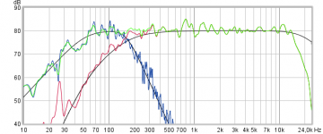
Green acoustic live situation, blue synthetic IR, rest is used drivers datasheet curves:
What i know is how 1st order can sound on design axis and how it can be a very pleasing listening but also how small error details when designing actual slope can add its distortion and often a pleasing sound signature because of the wide XO region and verse some even order slopes where XO region power response errors are same signature if in vertical axis we up over or below design axis then 1st order have non symmetrical power response errors up over or below design axis. In my eyes it looks problem with your build is everything above about 1kHz is a diffuse field of 10F and RS225 summing and nulls, you have a declining amplitude response as frq goes up which should show initial attack of SR not reaching a 100% number but rather be in the lower 70-90% region numbers then a rounding curve upwards down the timeline where it reach 100% number, what you share is a SR initial attack reaching 100% and never mind speculate why because it doesn't follow textbook how a declining amplitude response should be, so coupled with shared absolute phase distortion verse minimum phase and overlays of 10F/RS225 datasheets verse predictions and actual measurements, my guess is you cant no matter how hard you try up and down vertical axis find even one tiny little spot in space to declare here is a fair good 1st order acoustic slope so lets call it design axis and I'm within specs. Sorry if you forgot about details from the past but build needs more XO correction power to get there for even one point in space and actual culprit is probably the simple few components used for passive XO and then non ideal 8kHz reach by alu cone of RS225, for diy world have not much problem with the simple version and its own strange summing and distortion domain problem is transparence of real performance is far from marketing claims as a consumer product. About woofer say OEM called Dayton ask them for a woofer cover smooth as possible also within its break up area up to about 8kHz and any serious ripple should have character be passive component repairable then not shure cone material would be alu, AC-130F1 could maybe sum a lot nicer with 10F but low end transfer from those BW2 52Hz up to 92Hz then.
Attachments
Last edited:
Thanks for the explanation. I can clearly see the +60 degree phase response at high Hz - While tuning the delay added to the top-driver.
I have another noob question which has to do with what is going on before zero at the stepresponse tab. I start with a clean stepresponse of the individual driver(s) - In this case a 8" midbass in a small closed cabinet. After adjusting the freq-reponse with several PEGs in Rephase, I end up with the impulse not being nice before 0. What may be the explanation for this? Is is bad choice of crossoverpoint, EQ or something other than that. I have seen this several times now and dont have a clue why and most importantly how to avoid it (I quess it should not be there)?😕 😀
I have another noob question which has to do with what is going on before zero at the stepresponse tab. I start with a clean stepresponse of the individual driver(s) - In this case a 8" midbass in a small closed cabinet. After adjusting the freq-reponse with several PEGs in Rephase, I end up with the impulse not being nice before 0. What may be the explanation for this? Is is bad choice of crossoverpoint, EQ or something other than that. I have seen this several times now and dont have a clue why and most importantly how to avoid it (I quess it should not be there)?😕 😀
Attachments
- Home
- Loudspeakers
- Multi-Way
- S. Harsch XO