The Philips method actually measures the photodiode array current (indirectly by means of voltage across the resistor) and as such is 100% dependent on the reflected beam.
If your level drops down as it plays then it could be a mechanical issue, although a quick check would be to see if the level comes back if you start playing the disc from the start again.
It could also be the usual cap problems on the servo board (usually 33uf radial caps)
A good test is to measure the laser current directly but be careful. I would solder wires to the limiting resistor of the laser driver transistor (via a 47 or 100k for each solder to the resistor to avoid any possibility of 'spiking' the laser) and then bring those wires to your meter. Then see if the voltage across the resistor varies. If the diode is losing emission as it heats then the current will rise as the OPC (optical power control) tries to increase the current. A current of 45 to 55ma would be typical for the LT022MC diode which I think these use.
Hi Mooly thank you for the reply,
This doesn't seem to be a mechanical issue, but a Laser time ON issue. The swing arm is free and travel is smooth. I can play the first track as well as the last track and any in between and start and stop. If I stop for a while the voltage will have gone up, how much depends on laser off time and not unit off time.
I have changed the 47uf C112 which should be the equivalent to the 33uf cap in Philips players and I also changed T101 and no difference.
I can also measure a slow corresponding voltage drop at pin 1 of T101. It starts at over 8 volts and is mid 7 volts when the unit stops playing.
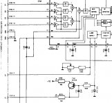
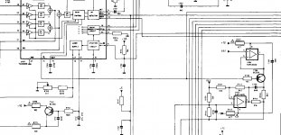
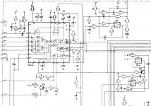
I will measure the current at the resistor you mention but I first need to know which one it is since it looks like there are a few. I am including cropped schematics of the area.
Thanks,
Mark K.
This doesn't seem to be a mechanical issue, but a Laser time ON issue. The swing arm is free and travel is smooth. I can play the first track as well as the last track and any in between and start and stop. If I stop for a while the voltage will have gone up, how much depends on laser off time and not unit off time.
I have changed the 47uf C112 which should be the equivalent to the 33uf cap in Philips players and I also changed T101 and no difference.
I can also measure a slow corresponding voltage drop at pin 1 of T101. It starts at over 8 volts and is mid 7 volts when the unit stops playing.
I will measure the current at the resistor you mention but I first need to know which one it is since it looks like there are a few. I am including cropped schematics of the area.
Thanks,
Mark K.
Attachments
Last edited:
Mine never saw 50mV. 20 was all it would do while adjusting the pot.
You are correct on the 47uf. There are no 33uf in there.
I removed and measured them all.
BTW, I played a disc last evening. About three tracks in, the sound became fuzzy. Just using it as a transport. The laser still illuminates.
You are correct on the 47uf. There are no 33uf in there.
I removed and measured them all.
BTW, I played a disc last evening. About three tracks in, the sound became fuzzy. Just using it as a transport. The laser still illuminates.
The resistor is R110, the 10 ohm to T101 collector. The voltage across that resistor should be essentially constant, only changing a little with the temperature of the laser diode. So after a few minutes playing it should be unvarying. Would expect somewhere around 0.55 volts.
I tested voltage across R110 and it slowly increased from approx. 2.35mv to 2.86mv after about 15 minutes and was pretty stable after that. The voltage across R101 continues to drop even after R110 stabilizes. Also R110 is a 18ohm .1 percent resistor.
I attached 100K resistors at each end of R110 for current monitoring and never got more than 14uA(yes that is micro amps). Maybe my voltmeter is faulty?
It takes about 30 minutes of playing before unit doesn't want to play anymore.
Mark K.
I attached 100K resistors at each end of R110 for current monitoring and never got more than 14uA(yes that is micro amps). Maybe my voltmeter is faulty?
It takes about 30 minutes of playing before unit doesn't want to play anymore.
Mark K.
Last edited:
So we are looking at your first picture... it looked like a 10 ohm (laptop) 🙂
The laser diode will draw around 55ma and so that equates to (V=I*R) which is 0.055*18 giving 0.99 volts. So that is the sort of ballpark figure you should see across that resistor.
We are not measuring current directly, we do it by calculation of the voltage across the known resistor.
It sound like a measurement issue at the moment if you are only seeing a few millivolts across that 18 ohm. Essentially the same current flows in R111 but its safer to measure across R110.
Make sure you have your meter set to DC volts when measuring. If you had it set to measure current then that could explain your reading.
2.3 volts across 18 ohm is 127 milliamps and that is way over what would be expected. That only leaves two possibilities:
1/ The laser diode is severely deteriorated and the increase is due to the OPC turning the current up to compensate.
2/ There is a problem with the drive circuitry and the feedback from the laser diode. That would be rare.
I would try adjusting the laser power (preset) purely to see if the control has an effect.
By 'effect' I mean on controlling the current and that means observing whether the voltage across the resistor can be turned down from where it is now.
If I turn down the Laser voltage the voltage across R110 only goes down a few tenths of a Volt. When the unit is close to dying around 10 to 15 mv across R101 at this time if I turn the laser pot all the way up I get about 40mv across R101. When cold it will start and play for about a half hour every time before it dies.
New observed behavior since I've been playing is It will hold voltage across R101 steady at around 50mv at start and then suddenly drop to 40mv at around 10 minutes of playing then continue to drop steadily until unit stops playing.
New observed behavior since I've been playing is It will hold voltage across R101 steady at around 50mv at start and then suddenly drop to 40mv at around 10 minutes of playing then continue to drop steadily until unit stops playing.
I would have expected that turning the preset down would have substantially reduced the current, and your readings suggest that isn't happening. A faulty laser diode is still the most likely scenario but its not a 100% certainty.
The voltage across R101 is determined solely by the intensity of the reflected beam from the disc.
The voltage across R110 is determined by the optical light output of the laser and the disc has zero influence on this. On a working player the voltage across this resistor can vary with temperature and also with aging of the laser. Whatever happens here should not show as any change in the voltage across R101. The fact that on your player it is changing suggests that the laser power control circuit has reached the limits of what it can correct. The laser is running at a high current already to achieve the set light output. It warms and the current automatically increases to compensate but then hits the limits of what is available. That is the point you see the voltage fall across R101 as the light output suddenly falls away as no more current is available.
One easily done test could be to try a little freezer spray (a can of inverted air duster works as well) on the laser drive chip and transistor. We are talking individual drips of the stuff here, not blasting the whole area.
You could also try a little on the housing of the laser diode but only a little. Just enough to cool the area. Sudden chilling will cause condensation on the internal face of the diode and stop it playing. Also do not allow overspray on the lens because cheap air dusters often use butane and that could fog coated optics (although I think the Philips radial arms were a pure glass lens).
Thank you Mooly for your time and consideration!
I'm not ready to give this one up for dead yet. So I will get some electronics freeze spray and report back when I get the chance.
Thanks again,
Mark K.
I'm not ready to give this one up for dead yet. So I will get some electronics freeze spray and report back when I get the chance.
Thanks again,
Mark K.
OK 🙂
(and practice with the spray. You can get this stuff to dispense virtually drop by drop which is what you need to do to avoid cooling to large an area)
(and practice with the spray. You can get this stuff to dispense virtually drop by drop which is what you need to do to avoid cooling to large an area)
I got some spray and carefully cooled components from the power supply to underneath the transport itself and very little change from the downward trend of the mv readings across R101. I did get some minor mv elevations from barely cooling the laser body itself, too much however causes condensation on the lens, but the effect wasn't enough and the trend continued.
I then dug out one of my spare CDM4's from a 6 disc changer and swapped swing arm with laser into the rotel cdm4 body and it works perfectly holding right around 50mv with very little deviation from start to finish.
Thanks for the help and now one more CDM4 symptom with a result for reference. DEAD/DYING LASER! Maybe the monitor diode?
Mark K.
Great that you have got a result  and a shame it looks like a duff laser 🙁
Yes, the monitor diode is integral on the same die as the laser and so it could be defective. We sort of forger how old these are now.
and a shame it looks like a duff laser 🙁Yes, the monitor diode is integral on the same die as the laser and so it could be defective. We sort of forger how old these are now.
Rotel RCD 855 Skipping
One of the posters here mentioned that there is a method to adjust the laser
and I assume the mechanism also. I didn't find the information about the
mechanism nor the laser in the user or the service manuals. I found some
information about service information.
The service information describes entering the Service Loop,
no problems there or with the other modes until I got to mode 4.
I get error 02 Focus Error: no TL pulse at start-up. (NB: TL = Track Loss).
However it doesn't address if I should load a disc at this step.
If so then I don't get any errors.
If I go through the process disc free, then I get the 02 error.
As this would be logical, because there isn't a disc present.
Is my thinking correct about this?
So it still skips. Debating weather to keep or send it back.
I don't know if there are CDM4/19 mechanisms around
and when working properly if the unit is worth keeping?
Cheers,
I'm not really familiar with the Rotel and so wouldn't like to say how deserving it is to have money spent on it although these early players did have a warmth and charm to them.
If you like it then go for it 🙂
The radial type mechs shouldn't really need any 'adjustment', and any there is, is simply mechanical alignment that once done (initial factory alignment) never needs looking at again.
Sounds like you may have other issues if you have replaced the mech and still have the same fault. Caps OK as they are usual suspects ?
I was looking around for the Sony alignment and test disc for it. I think it was
type 4 YEDS 18. Imagine that! caps being the usual suspects.
I didn't see any obvious signs hoping to avoid tearing into it.
I should have known. I don't know enough to like it or not
then found out it didn't have the s1 chip.
Cheers,
type 4 YEDS 18. Imagine that! caps being the usual suspects.
I didn't see any obvious signs hoping to avoid tearing into it.
I should have known. I don't know enough to like it or not
then found out it didn't have the s1 chip.
Cheers,
You don't need any special disc for working on CD players. The official test discs were simply discs that met the red book standard for reflectivity, weight, thickness etc.
99.5% of decent commercial discs will be fine, the odd one (out of 100's) can be down on reflectivity which shows as a low RF signal from that one disc only.
The caps on the servo boards under the mech were the usual problem ones on the Philips based machines. Typically small 33uF axial types although the Rotel may be different.
- Home
- Source & Line
- Digital Source
- Rotel RCD 855 repair