Ok, my best shot at explaining.
I removed the cover to watch what the CD did when it loaded and tried to read the TOC.
I noted that it spun backwards for about a second then gave up.
Next I removed the CD clamp assembly and the CD and watched for output from the laser. I noted it seemed dim, but I had never looked before.
I also noted that it hunted back and forth and up and down.
At this point I didn't know doodly squat about CD players, so I posted here after reading all the other 855 issue posts.
Then I googled CD player repair and found this:
https://www.repairfaq.org/sam/cdfaq.htm
It's very good. I learned a lot. So do check it out.
I found out from this site that two main things cause the disc to rotate backwards. Laser dead, and spindle motor drive circuit issues.
As I mentioned, I tested the motor itself with a power supply. It begins to rotate at approx. 2vdc. Switch the leads and it goes the other way.
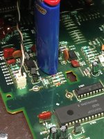
From the jizz-matic, I saw T102 and T103 are the motor drive transistors. Can't measure them in circuit so I removed them and viola, T103 was open collector to emitter.
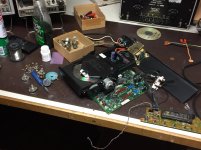
Of course all of this circuitry is under the transport. The two transistors in question can be seen in one of the photos. The other photo shows that I've made a "kit" out of my player......😀
I tried but had no luck finding a complete and legible schematic. Even paid for a download that turned out to be the same as one I got for free. I was refunded my money.
Good luck!
Ron
I removed the cover to watch what the CD did when it loaded and tried to read the TOC.
I noted that it spun backwards for about a second then gave up.
Next I removed the CD clamp assembly and the CD and watched for output from the laser. I noted it seemed dim, but I had never looked before.
I also noted that it hunted back and forth and up and down.
At this point I didn't know doodly squat about CD players, so I posted here after reading all the other 855 issue posts.
Then I googled CD player repair and found this:
https://www.repairfaq.org/sam/cdfaq.htm
It's very good. I learned a lot. So do check it out.
I found out from this site that two main things cause the disc to rotate backwards. Laser dead, and spindle motor drive circuit issues.
As I mentioned, I tested the motor itself with a power supply. It begins to rotate at approx. 2vdc. Switch the leads and it goes the other way.
From the jizz-matic, I saw T102 and T103 are the motor drive transistors. Can't measure them in circuit so I removed them and viola, T103 was open collector to emitter.
Of course all of this circuitry is under the transport. The two transistors in question can be seen in one of the photos. The other photo shows that I've made a "kit" out of my player......😀
I tried but had no luck finding a complete and legible schematic. Even paid for a download that turned out to be the same as one I got for free. I was refunded my money.
Good luck!
Ron
Attachments
Thanks Monk...This is great information...I appreciate you taking the time. Hopefully with this and some of the other info I've collected and read I think it may be time to take another shot at fixing my 855. I remember going through the different diagnostics tests, and it having a problem reading the TOC. I don't remember noticing improper rotation on the disc. I found my digital copy of the 855 manual, not sure if it's the same you found, it is difficult to read properly when you try to zoom in.
LOL...sorry �� my head was still in another thread where I was trying to give some help
So I got back to this and figured I should do the alignment as outlined in the RCD955 manual. I know you have all been on the edge of your seats waiting for this......😀
There are two adjustments. Laser Current and Focus Offset.
I had only messed with the current pot a little, so I followed the process for that.
I set the pot plus R108 to equal 1K.
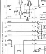
Then hit play and attempted to set the voltage across R101 to 50mV.
R101 is in series with the laser I assume. See attached.
It is a 4.7K resistor.
At any rate, this is quite low current.......
That said, with the disc spinning, I measured 20mV. As I adjusted to increase it, the disc stopped and the current went to 0. started over, adjusted the other way and below 10mV the disc stopped and the current went to 0.
So 20mV it is. I let it play the entire disc twice, and the volts stay steady. But it sure won't set to 50mV as described in the procedure.
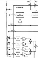
Basically, I think there is more going on here than a direct current adjustment. I have the Datasheet for the Photo diode signal processor TDA8808T but confess to not having paid attention in CD player class back in 1987. I was a spectrum analyzer tech.
Anyway, I'll put a DAC chip back in and see if it makes music.
There are two adjustments. Laser Current and Focus Offset.
I had only messed with the current pot a little, so I followed the process for that.
I set the pot plus R108 to equal 1K.
Then hit play and attempted to set the voltage across R101 to 50mV.
R101 is in series with the laser I assume. See attached.
It is a 4.7K resistor.
At any rate, this is quite low current.......
That said, with the disc spinning, I measured 20mV. As I adjusted to increase it, the disc stopped and the current went to 0. started over, adjusted the other way and below 10mV the disc stopped and the current went to 0.
So 20mV it is. I let it play the entire disc twice, and the volts stay steady. But it sure won't set to 50mV as described in the procedure.
Basically, I think there is more going on here than a direct current adjustment. I have the Datasheet for the Photo diode signal processor TDA8808T but confess to not having paid attention in CD player class back in 1987. I was a spectrum analyzer tech.
Anyway, I'll put a DAC chip back in and see if it makes music.
Attachments
The official Philips method for setting the laser current was awkward and convoluted. You are measuring the current (indirectly by measuring voltage) flowing in the photo-diode array when playing a test disc meeting Philips standards.
If you have twiddled the pot away from its original setting then the best you can hope for is to adjust it using a good commercial CD (and try more than one in case the one you pick is poor) and by setting the RF signal to an amplitude of approximately 1.2 volts peak to peak as measured on a scope. Use a properly compensated and correctly adjusted divider probe and a scope of at least 20MHz bandwidth.
If you have twiddled the pot away from its original setting then the best you can hope for is to adjust it using a good commercial CD (and try more than one in case the one you pick is poor) and by setting the RF signal to an amplitude of approximately 1.2 volts peak to peak as measured on a scope. Use a properly compensated and correctly adjusted divider probe and a scope of at least 20MHz bandwidth.
Ah. Got it.
My scope is a 7000 series mainframe and I have various plugin's.
It should meet those specs.
Thanks!
My scope is a 7000 series mainframe and I have various plugin's.
It should meet those specs.
Thanks!
I made this measurement at the input to the decoder. I get 1v P-P.
Scope is calibrated and the probe comp'd properly.
That's the max volts it will adjust to.
Adjusting the pot does improve the clarity of the signal. So I set it to look the best.
I used to have a Denon test CD, have no clue where that ever went......
Appreciate the help Mooly
Scope is calibrated and the probe comp'd properly.
That's the max volts it will adjust to.
Adjusting the pot does improve the clarity of the signal. So I set it to look the best.
I used to have a Denon test CD, have no clue where that ever went......
Appreciate the help Mooly
The pot for laser power should only adjust the amplitude, not the clarity.
This thread might give you a feel for how it all comes together:
http://www.diyaudio.com/forums/digital-source/226288-sony-cdp790-kss240-restoration-project.html
This thread might give you a feel for how it all comes together:
http://www.diyaudio.com/forums/digital-source/226288-sony-cdp790-kss240-restoration-project.html
I'll read it. Thanks.
Isn't it funny how things aren't supposed to do the things they do?
This thing is getting closer and closer to the recycle bin.
Isn't it funny how things aren't supposed to do the things they do?
This thing is getting closer and closer to the recycle bin.
Well, I took the laser assy apart and cleaned the mirror and the underside of the lens.
Didn't change the output wave form amplitude.
I got tired of having the thing spread all over the work bench so I put it back together.
Plugged the digital out into my DAC and I'll be dammed, it works.
I didn't want to waste the time putting a DAC chip in it not being sure it would play.
So down the road I'll stuff one in there and see how it sounds.
Current DAC is a pooged Phillips DAC960 that sounds very good, so I doubt this would ever equal that. But I happen to have another all stock DAC960 and what I really wanted was a transport anyway.
Ron
Funny, I was using this as a transport last night. Started sounding fuzzy, then went blap blap blap........disc quit spinning.......it's dead.
My foolishly tweaking the laser when I first started fooling with fixing it likely killed it.
RIP RCD855
My foolishly tweaking the laser when I first started fooling with fixing it likely killed it.
RIP RCD855
Maybe, but its by no means a certainty the laser has popped its clogs. Just treat it as any normal fault with no preconceptions.
Aren't Phillips CDM4/19 lasers assemblies available anymore? I've got a couple of spares for my 855 but haven't needed one yet.
Sent from my iPhone using Tapatalk
Sent from my iPhone using Tapatalk
I've got a Rotel 855 CDM4 question; I'm working on a spare for mine I bought recently and the laser voltage across R101 starts, from a cold start, at around 50mv then slowly drops to less than 20mv and cuts out completely. This takes about a half hour. Music is fine until nearly the cut out point. I've replaced a couple of caps and a transistor in the 8808 circuit but am waiting on some freeze spray for possible heat issues with components. Has anyone seen a laser die this way? I have not adjusted laser voltage. Just curious if I'm wasting my time.
- Home
- Source & Line
- Digital Source
- Rotel RCD 855 repair