Re: Supply for clock
I only see an LC filter, not a Pi filter
no, no, I'm not trying to be a smart *** 😉
Elso Kwak said:
Hi Bricolo,
Please use the raw digital supply. Don't use the analog supply, giving bad sound. My clock sounds best without pregulation. Pi-filters are on board.
😎
I only see an LC filter, not a Pi filter
no, no, I'm not trying to be a smart *** 😉
I only see an LC filter, not a Pi filter
I think the Pi filter comes from if there's a capacitor on the raw supply on the cdp pcb just before the supply gets to the clocks inductors. Then there's two caps in parallel and an inductor in between, I presume this is a Pi filter? I haven't actually ever seen a propper definition of a Pi filter...
The player should hhave some 9-16 raw supply before the +/-5V regulators
I measured just after the schottky bridges on the digital supply, and it was still around 5v. Bit strange I know as there are so many people using this source of supply for your clock.
Thanks for clearing up the whole grounding thing, I was a little confused after seeing a few references to attatching the signal 'floating', though I'm not exactly sure what this means.
Cheers all!
PIfilter and ?????????
But how can you get +5V from a 5V raw supply. Even a low drop regulator needs some voltage drop. What is the type of regulator your CDP is using?😕
Or maybe your measurement is wrong.

Hi, Yes that's a PI filter: the raw supply cap, the 2.2mH inductor and the 2200µF cap on the clock board.baggystevo82 said:
I think the Pi filter comes from if there's a capacitor on the raw supply on the cdp pcb just before the supply gets to the clocks inductors. Then there's two caps in parallel and an inductor in between, I presume this is a Pi filter? I haven't actually ever seen a propper definition of a Pi filter...
I measured just after the schottky bridges on the digital supply, and it was still around 5v. Bit strange I know as there are so many people using this source of supply for your clock.
Thanks for clearing up the whole grounding thing, I was a little confused after seeing a few references to attatching the signal 'floating', though I'm not exactly sure what this means.
Cheers all!
But how can you get +5V from a 5V raw supply. Even a low drop regulator needs some voltage drop. What is the type of regulator your CDP is using?😕
Or maybe your measurement is wrong.
Hi
Yeh my measurement could well be wrong!! I may be measuring in the wrong places, but I probed around all over the place on the digital side and couldn't find anything over 5v. I did think it strange that I could find no point of regulation!
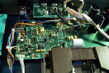
In this pic the raw AC is carried by the multicoloured wires, on the left I think is the rectifier for the digital stage, and on the right can be seen the two large caps for the analogue stage, as far as I know. Any suggestions as to where to poke my voltmeter?
Cheers again,
Steve
Yeh my measurement could well be wrong!! I may be measuring in the wrong places, but I probed around all over the place on the digital side and couldn't find anything over 5v. I did think it strange that I could find no point of regulation!
In this pic the raw AC is carried by the multicoloured wires, on the left I think is the rectifier for the digital stage, and on the right can be seen the two large caps for the analogue stage, as far as I know. Any suggestions as to where to poke my voltmeter?
Cheers again,
Steve
Attachments
Help!
Do me a favor and get a servicemanul for your player.
On the left rear I see a blue cap that might be for the digital supply but poking around without knowing what you are doing is not my style......
Hi Steve,baggystevo82 said:Hi
Yeh my measurement could well be wrong!! I may be measuring in the wrong places, but I probed around all over the place on the digital side and couldn't find anything over 5v. I did think it strange that I could find no point of regulation!
In this pic the raw AC is carried by the multicoloured wires, on the left I think is the rectifier for the digital stage, and on the right can be seen the two large caps for the analogue stage, as far as I know. Any suggestions as to where to poke my voltmeter?
Cheers again,
Steve
Do me a favor and get a servicemanul for your player.
On the left rear I see a blue cap that might be for the digital supply but poking around without knowing what you are doing is not my style......
Hi,
Yes a service manual would be lovely!! Not a clue how to go about obtaining one though...
As far as the poking around goes, yes I am very much a beginner, but I have to learn somehow, and so far the only real ways I've found is experimentation (I haven't managed to break anything yet ) and reading up on forums like this, and asking lots of questions, probably a few too many! I look forward to the day when I can look at the insides of a CDP and know exactly how everything works!! one day.... 🙂
Yes a service manual would be lovely!! Not a clue how to go about obtaining one though...
As far as the poking around goes, yes I am very much a beginner, but I have to learn somehow, and so far the only real ways I've found is experimentation (I haven't managed to break anything yet
) and reading up on forums like this, and asking lots of questions, probably a few too many! I look forward to the day when I can look at the insides of a CDP and know exactly how everything works!! one day.... 🙂Steve,
PS V+ to clock V+
PS GND to clock GND
PS V- to clock V-
Coax Cable Clock -> Player, Shield connecting clock ground
to player ground where the two caps of the original oscillator were removed.
Michael
I´m not Elso, and noone who knows, but I got my best result connecting a seperate PS:baggystevo82 said:Oooh one more question! 🙂
Elso, or anyone else who knows, how would you hook up the ground from the clock, if at all, now it's run from a seperate supply?
Cheers
PS V+ to clock V+
PS GND to clock GND
PS V- to clock V-
Coax Cable Clock -> Player, Shield connecting clock ground
to player ground where the two caps of the original oscillator were removed.
Michael
Cheers Michael,
Does anyone think it would matter, just for testing, that I hooked it up with just ordinary single core for the signal, and another wire for the ground? Could this be a reason why it doesn't work properly yet? I can locate the clock so the lead length is only an inch or so, so would the bulkiness of coax be worth it over such a short distance?
Cheers everyone once again 🙂
Stevo
Servicemanuals
You could contact the Rotel importer in your country or the many firms that sell servicemanuals on the net.
Some studying in Horowitz and Hill, the Art of Electronics, Cambridge University Press wouldn't hurt....
😎
Hi,baggystevo82 said:Hi,
Yes a service manual would be lovely!! Not a clue how to go about obtaining one though...
As far as the poking around goes, yes I am very much a beginner, but I have to learn somehow, and so far the only real ways I've found is experimentation (I haven't managed to break anything yet
You could contact the Rotel importer in your country or the many firms that sell servicemanuals on the net.
Some studying in Horowitz and Hill, the Art of Electronics, Cambridge University Press wouldn't hurt....
😎
Yeh I'll have a look soon I think. I'm also taking all the electronics modules I can at uni too, which is helping quite a lot. We get to build a simple DAC at the end of this term 🙂
Stevo
Stevo
Woops!!!
Hi Everyone again, well I found out why it didn't work!! I assumed that the Collector, Base & Emitter legs would be in the same place for the npn and pnp transistors....apparently this isn't so, according to their datasheets anyway, it looks as though the collector and emitter swap places. 😱
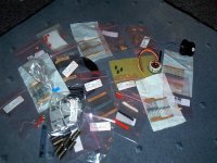
Ahh well time for another go, this time with power supply on board and p2p wiring on a matrix board similar to here:
p2p Kwak Clock
Hopefully Ill have more luck this way than last time, and at least if I make a mistake it's easier to change components/layout.
It would be good if any of you could share your experiences with p2p wiring clocks, any tricks, snags etc.
Again a big thankyou goes out to Elso and everyone else who's helped.
Ahh well I best get started, all the parts have just arrived 😀
Cheers,
Steve
Hi Everyone again, well I found out why it didn't work!! I assumed that the Collector, Base & Emitter legs would be in the same place for the npn and pnp transistors....apparently this isn't so, according to their datasheets anyway, it looks as though the collector and emitter swap places. 😱
Ahh well time for another go, this time with power supply on board and p2p wiring on a matrix board similar to here:
p2p Kwak Clock
Hopefully Ill have more luck this way than last time, and at least if I make a mistake it's easier to change components/layout.
It would be good if any of you could share your experiences with p2p wiring clocks, any tricks, snags etc.
Again a big thankyou goes out to Elso and everyone else who's helped.
Ahh well I best get started, all the parts have just arrived 😀
Cheers,
Steve
Attachments
P2P Clock
Hi Steve,
The nicest P2P Kwak-Clock I have seen was on Yeo's site:
http://www.diyparadise.com/clock.html
Yeo also gives nice pinouts pictures of the parts used.
BTW BC550C & BC560C have the same pinouts!
😎
Hi Steve,
The nicest P2P Kwak-Clock I have seen was on Yeo's site:
http://www.diyparadise.com/clock.html
Yeo also gives nice pinouts pictures of the parts used.
BTW BC550C & BC560C have the same pinouts!
😎
Thanks!! Good link, and just as well I looked! I got confused with the pinouts of BC560C as they call collector p1, base p2 and emitter p3, which is opposite of BC560 (that whole BC560 BC560C thing again 😡 ). However the pins are physically in the same place on all of them, so i need to rework this design again, hehe. Cheers for that or I would have done it wrong again!
Thanks,
Steve
😡 ). However the pins are physically in the same place on all of them, so i need to rework this design again, hehe. Cheers for that or I would have done it wrong again!Thanks,
Steve
Powersupply for Clock
Hi Steve,
I did not check or verify your schematic. Contrary to all clock mongers I suggest using the players raw digital powersupply for the clock.
😎
baggystevo82 said:Hello, another question....
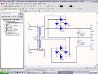
This should work shouldnt it?
Steve
Hi Steve,
I did not check or verify your schematic. Contrary to all clock mongers I suggest using the players raw digital powersupply for the clock.
😎
I know, and I would if I could, but as I said earlier I was having trouble finding a suitable supply. Im sure lots of the manufacturers that make and sell clocks may well just do it for money, but in this case I'm doing it out of necessity (or just being too stupid to find the raw digital supply on my cdp, hehe). Im pretty sure that schematics OK though, I trawled through some books looking for the layout used for gettin -ve-0-+ve supplies, and the ones I found matched mine.
Thanks,
Steve
Thanks,
Steve
Elso,
I biuld my KC today, not really a KC7, not really a KC6
Since I haven"t recieved my 1uF PP caps, I used a second 2200uF instead.
I'm measuring with a home made probe like you told me, with a 50 ohm coax cable terminated with 50 ohm at the scope side.
It's connected at the output of the comparator
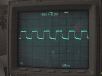
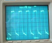
That's what I get: something looking like a square wave, the frequency is ok. But it's only 1.2V pp
I'm powering the clock with 2 new 9V cells
I'll post pictures of the board later
I biuld my KC today, not really a KC7, not really a KC6
Since I haven"t recieved my 1uF PP caps, I used a second 2200uF instead.
I'm measuring with a home made probe like you told me, with a 50 ohm coax cable terminated with 50 ohm at the scope side.
It's connected at the output of the comparator
That's what I get: something looking like a square wave, the frequency is ok. But it's only 1.2V pp
I'm powering the clock with 2 new 9V cells
I'll post pictures of the board later
Attachments
Square wave
Hi Bricolo,
You got a nice square wave!
The wave form is AOK. I have seen worse waveforms in dataheets. Don't worry about the amplitude. The 50 Ohm is apparently a hefty load for the comparator. If you connect the CD you will see it works. Good luck.
Bricolo said:Elso,
I biuld my KC today, not really a KC7, not really a KC6
Since I haven"t recieved my 1uF PP caps, I used a second 2200uF instead.
I'm measuring with a home made probe like you told me, with a 50 ohm coax cable terminated with 50 ohm at the scope side.
It's connected at the output of the comparator
That's what I get: something looking like a square wave, the frequency is ok. But it's only 1.2V pp
I'm powering the clock with 2 new 9V cells
I'll post pictures of the board later
Hi Bricolo,
You got a nice square wave!
The wave form is AOK. I have seen worse waveforms in dataheets. Don't worry about the amplitude. The 50 Ohm is apparently a hefty load for the comparator. If you connect the CD you will see it works. Good luck.
Nice 🙂
You're right, the 50 ohm seems to be a hard load for the comparator
When I connect my DMM to the output (while it's connected to the probe) it displays 0.7V
when I connect it to the complementary output (not connected), I have 1.9V
Are you sure the squarewave it so nice? That's how it looks with more sensitivity:
Attachments
Square Wave
😎
Yes, remember the flanks are being used by the CDP.Bricolo said:Nice 🙂
Are you sure the squarewave it so nice? That's how it looks with more sensitivity:
😎
- Status
- Not open for further replies.
- Home
- Source & Line
- Digital Source
- Rotel RCD-02 Kwak-Clock upgrade