I've got a Rotel RB850 amplifier, to which I made some small mods years ago (new Audioquest power cord, real binding posts and RCA jacks). The amp uses dual transformers and rectifiers. I have the schematic, what do the experts think, is this amp a good design or not? Is it worth upgrading some of the parts (I was thinking of input cap, feedback resistor, and 0.22 ohm emitter resistors in the output stage, and perhaps Schottky rectifiers if I can find the proper rating of what is in there now). Or is the design so old that it should be tossed into the basement system?
Thanks,
RonS
Thanks,
RonS
Attachments
Hi,
Besides the usual changes of compnents for better ones, you can add a 100uF capacitor across D602 (+) and R608 (GROUND).
I think than read R608 in the source current for the differential input.
This down the noise floor in the input, generated for the output in the supply, and the ressult are tath are show new information, and appear a 3D image. Almost magic.
But you need made before the other improvements for apreciate all this.
Happy days,
Raúl Couto
Hi Raul,
Yes, D602+ is followed by D604 then R608 to ground, in the current source for the input differential pair. So I should bypass the entire string of D602 to R608 with on cap, 100uF, about 100V to be safe? And this will lower the noise floor? That's what I want, lower noise, more 3D magic 🙂
Anything else besides parts upgrades, and what parts would you upgrade? I was told that maybe C616, 5pF should be improved. What about a seperate regulated power supply for the input diff. pair, like the Ryan Adcom upgrade?
Thanks again,
RonS
Regulator
The Adcom's Kit Ryan upgrade was for the whole amp, a high current regulator, not just for the first stages.
Carlos
The Adcom's Kit Ryan upgrade was for the whole amp, a high current regulator, not just for the first stages.
Carlos
Hi RonS
The usual parts for upgrade are the capacitors.
For small values, less than 10nF, the best election are the Styroflex, or the Ceramic NPO.
For up to 1uF use polipropilene, or any film and foil: MkC, MKT. The series 470 from BC componennts (Philips) are a good election.
For higer values use low Z electrolitics. The minimun can be the Panasonic FO.
If you can, please, read the series of articles about "Sound of Capacitors" tath Mr Cyril Bateman have publised from this June, perhaps are the best work about capacitors tath have never writen.
The other upgrades: Schottkys, etc. are also a good idea.
Happy days,
Raúl Couto
Sorry,
"Sound of Capacitors" are pubished in Electronics World & Wireless World.
Happy days,
Raúl Couto
"Sound of Capacitors" are pubished in Electronics World & Wireless World.
Happy days,
Raúl Couto
Rotel circuit
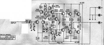
Am I wrong or there should be a connection point between Q612's collector and the trace that goes to Q618's base?
What does that star close to C616 mean? What do they say on the diagram?
Carlos
Am I wrong or there should be a connection point between Q612's collector and the trace that goes to Q618's base?
What does that star close to C616 mean? What do they say on the diagram?
Carlos
Carlos,
I can't comment on the connection between Q612 and Q18, that's beyond my comprehension 🙁
As to C616, the star indicates that this part should be used everywhere in the world except for the UK. It's a 5pF cap. Any ideas about this one?
What do you think of the circuit in general, and the quality of the transistors themselves?
Cheers,
RonS
carlmart
Hei Carlmart!!
You are right, there should be a connection point between Q612's collector and the trace that goes to Q618's base...of course!!!
Regards
Jorge Santos
Hei Carlmart!!
You are right, there should be a connection point between Q612's collector and the trace that goes to Q618's base...of course!!!
Regards
Jorge Santos
Re: carlmart
Thers should not! The 5p-cap is HF-feedback. 🙂
Tube_Dude said:Hei Carlmart!!
You are right, there should be a connection point between Q612's collector and the trace that goes to Q618's base...of course!!!
Regards
Jorge Santos
Thers should not! The 5p-cap is HF-feedback. 🙂
raul_77 wrote
If one does this, then there is nothing improved within the current source (what I think was Raul's intention). It would be simply bypassing the positive power supply rail (it is however never bad to bypass power supply voltages locally on the PCB, but then do this for "the other side" as well).
If you want to improve the current-source without changing it's topology then you can capacitively bypass the two diodes, but not R608 - for heaven's sake.
Regards
Charles
Besides the usual changes of compnents for better ones, you can add a 100uF capacitor across D602 (+) and R608 (GROUND).
If one does this, then there is nothing improved within the current source (what I think was Raul's intention). It would be simply bypassing the positive power supply rail (it is however never bad to bypass power supply voltages locally on the PCB, but then do this for "the other side" as well).
If you want to improve the current-source without changing it's topology then you can capacitively bypass the two diodes, but not R608 - for heaven's sake.
Regards
Charles
Re: Re: carlmart
To have a feedback there should be something going forward. So how do you move forward from Q612 to Q618?
If C616 is the only path forward, then the UK audipohiles will have a serious problem because there's not C616 there.
Carlos
Morello said:
>Thers should not! The 5p-cap is HF-feedback. 🙂
To have a feedback there should be something going forward. So how do you move forward from Q612 to Q618?
If C616 is the only path forward, then the UK audipohiles will have a serious problem because there's not C616 there.
Carlos
phase_accurate said:If you want to improve the current-source without changing it's topology then you can capacitively bypass the two diodes, but not R608 - for heaven's sake.
Regards
Charles [/B]
Charles, looking at the schematic again, I see that you are correct, if I bypass from D602 to R608, all I'm doing is putting some local power supply bypassing, not improving the current source. So what you are saying is that I should bypass only the two diodes. What value do you recommend, and should it be a polarized or non polarized cap? What does this do, does it make the diodes quieter?
Any other suggestions on improving the amp, or the current source? I don't mind making minor surgery, but there's not much point in changing the entire thing is there 😉
Thanks,
Ron
Re: Re: Re: carlmart
The 5p-cap should be tied to the collector.😎
carlmart said:
To have a feedback there should be something going forward. So how do you move forward from Q612 to Q618?
If C616 is the only path forward, then the UK audipohiles will have a serious problem because there's not C616 there.
Carlos
The 5p-cap should be tied to the collector.😎
To morello!!
hei morello!!
sorry but you don´t have a clue of amplifier design...
You are totally wrong!!!
If the collector of Q612 don't connect to the base of Q618 the circuit can´t work at all!! So simple as that!!!
If you have any idea of what you are talking about, you will know that Q616 are the VAS (voltage amplifiyng stage)...Q608 and Q610 the CCS (constant current source)...Q614 the multiplifier of VBE...and this need's to work toghether and conected....of course!!!...
I sugest you before negating what other people say that you read a good book as : The Art of Electronics of Horowitz and Will that are a good beeguiners book...in order that you have some knowlege of what you are talking about!!!

Jorge Santos
hei morello!!
sorry but you don´t have a clue of amplifier design...
You are totally wrong!!!
If the collector of Q612 don't connect to the base of Q618 the circuit can´t work at all!! So simple as that!!!
If you have any idea of what you are talking about, you will know that Q616 are the VAS (voltage amplifiyng stage)...Q608 and Q610 the CCS (constant current source)...Q614 the multiplifier of VBE...and this need's to work toghether and conected....of course!!!...
I sugest you before negating what other people say that you read a good book as : The Art of Electronics of Horowitz and Will that are a good beeguiners book...in order that you have some knowlege of what you are talking about!!!
Jorge Santos
Re: To morello!!
Are 14 years old?
First of all I would like to tell you that I have been designing both sold stae and tube gear for att least 15 years!
Please, calm down a little bit.
I mixed up two numbers in the schematics. I feel sorry for that.
I belive that such can happen anyone.
The Art of Electronics? That is one of the most strange book I have seen. It i s a giude to approxiamtion!🙁
Please, bahve yourslef!
Tube_Dude said:hei morello!!
sorry but you don´t have a clue of amplifier design...
You are totally wrong!!!
If the collector of Q612 don't connect to the base of Q618 the circuit can´t work at all!! So simple as that!!!
If you have any idea of what you are talking about, you will know that Q616 are the VAS (voltage amplifiyng stage)...Q608 and Q610 the CCS (constant current source)...Q614 the multiplifier of VBE...and this need's to work toghether and conected....of course!!!...
I sugest you before negating what other people say that you read a good book as : The Art of Electronics of Horowitz and Will that are a good beeguiners book...in order that you have some knowlege of what you are talking about!!!
Jorge Santos
Are 14 years old?
First of all I would like to tell you that I have been designing both sold stae and tube gear for att least 15 years!
Please, calm down a little bit.
I mixed up two numbers in the schematics. I feel sorry for that.
I belive that such can happen anyone.
The Art of Electronics? That is one of the most strange book I have seen. It i s a giude to approxiamtion!🙁
Please, bahve yourslef!
No i'm 49 yeasr old!!!
I begin making amplifiers (Tube-mosfet-bipolars) at 13 years old...
I can design amplifiers in any of this categories...so...
I'm not hungry...i was only defending my point of view ...witch you agred later!
but as you say...that you are sorry...that's oK ...
All is well when finish well...as americans says "Happy end"
No hard Feelings!!!
Jorge Santos
Dear Tube_Dude,
Thanks for your reply. I think we have a lot in common regarding electronics. Let us have some nice discussions here.
Can yout tell me why only one of the verisons uses the 5pF-cap ?
Best regards\Joe
Thanks for your reply. I think we have a lot in common regarding electronics. Let us have some nice discussions here.
Can yout tell me why only one of the verisons uses the 5pF-cap ?
Best regards\Joe
Gentlemen,
I'm glad we got this back on track 🙂
Now, can we discuss how to improve this amplifier? What is the purpose of the 5pF cap, should it be upgraded, and what else can be done to improve the amplifier? Should D602+604 be bypassed?
Thanks!
RonS
I'm glad we got this back on track 🙂
Now, can we discuss how to improve this amplifier? What is the purpose of the 5pF cap, should it be upgraded, and what else can be done to improve the amplifier? Should D602+604 be bypassed?
Thanks!
RonS
- Home
- Amplifiers
- Solid State
- Rotel RB850 Still Current? Schematic Included