I suppose guys, that I could remove the amp board, remove every component from it, testing each as I go and then completely rebuild the board, replacing any components that were found to be dead/out of spec. Is this a course that some people take ? I'm just looking at it from a mechanic's viewpoint.
Btw, since my little shorting incedent I've noticed that the rails from power supply board to the amp board are now both reading the 33.3v that the schematic says they should, and not the 39v they used to??!
Btw, since my little shorting incedent I've noticed that the rails from power supply board to the amp board are now both reading the 33.3v that the schematic says they should, and not the 39v they used to??!
I suppose guys, that I could remove the amp board, remove every component from it, testing each as I go and then completely rebuild the board
Don't do that 🙂 That would be the worst possible thing to do and would almost certainly cause far more problems. Fault finding is all about gathering evidence and that means voltage checks and then if needed writing those voltages onto the circuit diagram so it all makes sense.
Btw, since my little shorting incedent I've noticed that the rails from power supply board to the amp board are now both reading the 33.3v that the schematic says they should, and not the 39v they used to??!
You need to start with a clean sheet. Power the amp up, work on just one channel at a time. The rails might be lower because current draw may have increased with a fault (and that pulls the voltage down). Basic checks with the amp can also be done. Check that the output transistors at least do not read short circuit from C to E and check the 0.22 ohm resistors are intact and not open.
Also we always recommend use of a DBT (dim bulb tester) when faced with problems like this.
Hi Mooly. Well, I took a lot of measurements but then re read your post and realised you meant with the amp turned on.
Oh well, I'll tell you what I got and re do it all when I get some time.
All eight of the .22 ohm resistors gave me .6 with the meter set to 200 ohm (the lowest setting).
The eight output transistors measured across c/e and then e/c (meter set to diode) read as follows q618 c/e 620 e/c ol
q622 c/e 620 e/c ol
q620 c/e 0 e/c 0
q624 c/e 0 e/c 0
q617 c/e 620 e/c 1200
q621 c/e 620 e/c 1240
q619 c/e 620 e/c ol
q623 c/e 625 e/c ol
Sorry to have miss read your reply. On the plus side I'm beginning to understand the diagram
and can now recognize the various components and see where they are, (not that I fully understand what they all do!). Cheers for all the help.
Yes 🙂 and they would be voltage measurements, not resistance checks.Well, I took a lot of measurements but then re read your post and realised you meant with the amp turned on.
If they all read the same then most likely they are OK. Your meter may lack accuracy at very low ohm values and you also have the meter lead resistance added to the result. Your meter should show 0.00 ohms (ideally) if you short the probes on that range.All eight of the .22 ohm resistors gave me .6 with the meter set to 200 ohm (the lowest setting).
The diode check range actually passes a small test current between the probes and the display reads the resulting voltage between the probes. OL on the display means the voltage between the probes is above the point the display can show a reading. In this case it means at least there is not a short.q622 c/e 620 e/c ol
These however seem to be shorted. 0 means no volt drop between the probes and that would be due to a short.q620 c/e 0 e/c 0
q624 c/e 0 e/c 0
A general comment... because your amp uses parallel pairs of output transistors it is perfectly feasible to get it all working with just one pair fitted per channel. Of course any other issues have to be fixed as well but a shorted output transistor (or two) doesn't mean you can't continue.
And don't forget about using a DBT as I mentioned earlier. It saves damaging high currents flowing and blowing output transistors while fault finding.
Hi Mooly, thanks for all the help. So I researched the dim bulb tester and knocked one up. Now it's made I can't find an incandescent bulb anywhere! Another thing; I read that I should use a bulb roughly the same wattage as the amp's cosumption?
If that's correct then going by the owner's manual i'd need a 310 w bulb! That can't be right, can it?
Re, running on one less set of transistors, I'm aiming to get this amp working as it did when new. The cost of any required components isn't much of an issue as far as I can see from looking at various suppliers sites. I'm not interested in krytonite plated boutique caps ond so on, but I would like to finish this project properly and to spec. Away for the weekend but will take powered up readings as soon as poss (and when I've found a 300w bulb!)

Try a 60 or 100 watt bulb 🙂 Those cover most applications.
The amp should draw little current when idling normally.
The bias adjust preset may need turning to minimum bias to force a low current draw and the amp would still work normally assuming no faults. There seem to be different versions of the amp and the bias preset arrangement. On both versions minimum bias current is achieved when the resistor is set to maximum resistance. This is important.


Hi Mooly. Finally tracked down a 100w bulb. On first powering up it was very bright. I rotated both bias vrs to maximum which lowered the brightness a little. Re took measurements as follows; q618 c/e 34v
q622 c/e 34v
q620 c/e 0v
q624 c/e 0v
q617 c/e .8v
q621 c/e .8v
q619 c/e 31.5v
q623 c/e 32.1v
The .22 ohm resistor readings varied; r632 80 ohm
r636 .8 ohm
r634 32 ohm
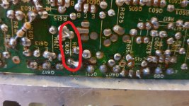
r638 3 ohm I noticed it seems to be solder joined to other comps (pic), unlike the others.
r631 34 ohm
r635 .6 ohm
r633 1.5 ohm
r637 1.4 ohm

I slipped the probe when taking the readings (again), and now the dbt is glowing very dim. (That's good isn't it?)
Currently getting 17v one one channel and -37 on the other.
I feel like a child who's found a gun. I want to play with it but I don't really understand what it does!
q622 c/e 34v
q620 c/e 0v
q624 c/e 0v
q617 c/e .8v
q621 c/e .8v
q619 c/e 31.5v
q623 c/e 32.1v
The .22 ohm resistor readings varied; r632 80 ohm
r636 .8 ohm
r634 32 ohm
r638 3 ohm I noticed it seems to be solder joined to other comps (pic), unlike the others.
r631 34 ohm
r635 .6 ohm
r633 1.5 ohm
r637 1.4 ohm

I slipped the probe when taking the readings (again), and now the dbt is glowing very dim. (That's good isn't it?)
Currently getting 17v one one channel and -37 on the other.
I feel like a child who's found a gun. I want to play with it but I don't really understand what it does!
I slipped the probe when taking the readings (again), and now the dbt is glowing very dim. (That's good isn't it?)
If the slip of the probe permanently changed the brightness then it has done something it shouldn't.
Currently getting 17v one one channel and -37 on the other.
In order to help we have to know which version you have because although the circuit design is broadly similar between the two, the component reference are totally different. See post #27 🙂 You will see the transistor reference numbers differ.
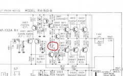
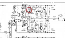
Ok, I'm sure that I have the straight ra-840. This would be the 180800.jpg screenshot. The ra-840 b was (visually) entirely different with no tone controls and two transformers. The screenshot for that (154.jpg) shows, as you mentioned, the suffix E,D on the transistors which is omitted from the ra-840 diagram.
OK, thanks 🙂
Lets work on the odd numbered channel (and remember to use the bulb tester at all times the amp is powered)
Begin again and with the amp OFF measure each of the 0.22 ohm resistors in circuit (to begin with). Are they all OK? They are so low in value they should read almost the same as you just shorting the probes together on many meters. You need a good meter to resolve very low ohms.
With your meter on the DIODE range measure from C to E on all four output transistors. C is the middle leg and E is the one on the right (that goes to the 0.22 ohm) as viewed from the front of the transistor. Do any read short circuit which would a very low reading on the diode range?
If they do read short you are going to have to isolate them all to determine which ones are short. It could one or more. The easiest way to do that is to just lift one end of each 0.22 ohm resistor to isolate the emitter. Now read each transistor again from C to E to determine which are short.
You should then recheck the 0.22 ohms while they are isolated to make sure none of those are open.
(if the 0.22 ohm appeared OK originally then if one transistor is short it will make its companion look short as well and also make it seem the 0.22 ohm was OK when in fact that could be open as well... if that makes sense 🙂 It is because the pairs of transistors are in parallel they can do that)
Lets see where that gets you.
Ok Mooly, I've covered the steps you gave me.
All the resistors read .6 ohm in circuit.
All the resistors read .6 ohm isolated.
Transistors in circuit read c to e meter set to diode; Q617 = 640
Q621 = 640
Q619 = open circuit (ref my meter's manual, ie, just a no.1)
Q623 = open circuit
Transistors isolated read c to e meter set to diode; Q617 = No reading, open, short?
Q621 = No reading, open, short?
Q619 = 1220 and climbing very slowly.
Q623 = 1220 and climbing very slowly.
We'll say the resistors are OK. 0.22 is very to measure on many meters and you have the lead and probe resistance to account for as well.
None of the transistors would appear to be short. That would give a reading the same as you shorting the probes which would be something like 0.00 or 0.01
Can you repeat this measurement but this time make sure the black meter lead goes to the collector (middle pin) and the red lead to the emitter. If they are isolated they should read open (same as the probes not connected)
I think they will be OK but its good experience. The polarity of the test voltage matters as to what readings you should see. The '640' you measured for Q617 and Q623 in circuit I think will be be you reading the diode D605 which is in inverse parallel with the transistors.
Take away point is that I think these are all OK.
That means we need to do voltage checks with it switched on next.
None of the transistors would appear to be short. That would give a reading the same as you shorting the probes which would be something like 0.00 or 0.01
Q619 = 1220 and climbing very slowly.
Q623 = 1220 and climbing very slowly.
Can you repeat this measurement but this time make sure the black meter lead goes to the collector (middle pin) and the red lead to the emitter. If they are isolated they should read open (same as the probes not connected)
I think they will be OK but its good experience. The polarity of the test voltage matters as to what readings you should see. The '640' you measured for Q617 and Q623 in circuit I think will be be you reading the diode D605 which is in inverse parallel with the transistors.
Take away point is that I think these are all OK.
That means we need to do voltage checks with it switched on next.
Hi Mooly, I repeated the checks making sure that the black lead went to the middle pin and the red to the right hand pin. (looking from the front). All four readings were the same. Q619 and 623 start at around 800 and top out around 1220. Q617/621 both no reading.
Hmm. The quick version... the PNP transistors (Q619 and Q623) should read open between C and E provided they are isolated from the board. The same applies to the NPN's (Q617 and Q621). The NPN's would be tested with the Red lead to the collector for a typical DVM
What sort of meter are you using? Not an analogue one is it? Analogue ones usually have 'reversed polarity' at the test leads terminals when on ohm ranges and they often use a higher test voltage.... however......
I think we will have to just have to move on from that 🙂
Just to be sure I've just tried what I have said with two different DVM's and a few PNP power transistors and all read open between C and E as expected. An analogue meter would be very different to use.
Where next... I think you are going to have to power the amp up and again concentrate on just the one channel we are working on now. If both pairs of output transistors are physically removed then just refit one pair only (one upper NPN and one lower PNP), solder them in and power up with the bulb tester. The bulb should be dim. If it is not we will try a few quick tricks to see where the overload is.
OK Mooly, I have a draper dmm 200 (digital). I may be a bit confused, the transistors aren't removed. But the emitter leg of each has been removed from it's relative .22 ohm resistor as per your suggestion. Did you want me to physically remove all the transistors?
I think we move on 🙂 99% of failures of power transistors are them failing short circuit and that obviously hasn't happened. I think you are seeing some effect of conduction via the base as that is still in circuit.
Lets get it powered up and do some voltage checks. As you isolated just the emitter resolder that back so that all is connected.
Providing it powers up OK (bulb dim) we always begin by confirming the supply voltages. Look at the circuit. You can check that easily by measuring on D605 and D607.
What rail voltages do you have?
Remeasure the DC offset at the output (on fuse F601). What is the offset?
Measure the DC voltage on R617. Do two readings, one to each end. What do you have?
Ok Mooly, so with the resistors soldered back in and powered on (dim bulb) we have; D607 = 48v
D605 = 10.5v
F601 = 18v
f602 = - 29v
R617 = -2.5v and +2.5v measured from each end.
D605 = 10.5v
F601 = 18v
f602 = - 29v
R617 = -2.5v and +2.5v measured from each end.
We need to get on top of these measurements as something is going amiss here 🙂 Lets go through it slowly.
Look at the circuit:

D607 connects between the negative rail and the amplifier output. This means the voltage measured on D607 anode (the end without a stripe that goes to the negative rail) and using ground (chassis) as a reference point should be no more than around -33 volts and a bit less with a dim bulb dropping the mains a bit. Now you measure 48 volts here. So something is amiss. Have I got the correct circuit? It is the standard RA 840 I'm using for this.
(Are you using the chassis (the zero volt line or 'ground) as the reference point for these measurements. That means the black meter lead goes here. The voltages you are seeing could perhaps be explained away if you were using F601 as the reference point)
Again look at the circuit...
D605 should see the positive rail on the end with a stripe (about +33 volts)
Do all the component references on the circuit diagram appear correct for for amp?
Look at the circuit:
D607 connects between the negative rail and the amplifier output. This means the voltage measured on D607 anode (the end without a stripe that goes to the negative rail) and using ground (chassis) as a reference point should be no more than around -33 volts and a bit less with a dim bulb dropping the mains a bit. Now you measure 48 volts here. So something is amiss. Have I got the correct circuit? It is the standard RA 840 I'm using for this.
(Are you using the chassis (the zero volt line or 'ground) as the reference point for these measurements. That means the black meter lead goes here. The voltages you are seeing could perhaps be explained away if you were using F601 as the reference point)
Again look at the circuit...
D605 should see the positive rail on the end with a stripe (about +33 volts)
Do all the component references on the circuit diagram appear correct for for amp?
- Home
- Amplifiers
- Solid State
- Rotel RA-840 DC voltage on one channel