Close and appropriate examination of data reveals that measurement was made in very live room.
How did you get first reflections to -40dB?
Microphone at 9"
I don't get such clean results even when measuring so close. How close was the nearest boundary?
Is 23cm even outside your speaker's near field?
Seems like the intermingling of direct/anechoic "speaker correction" and "room correction" is causing a lot of trouble for this discussion. Should we step back?
So, does that just leave "can IIR EQ be used for 'room correction', and how to best do that if so"? as the topic? Shouldn't we be discussing just that, assuming a ideal speaker?
Obviously they can be used for speaker correction. Not necessarily easy for DIYers, but still straightforward. Some people want to bring in FIR filters for crossover, and to correct phase at the edges of the speaker bandwidth, which seems reasonable. Some people want to use FIR for everything, which seems less reasonable, but that's not the topic anyway, right?Hi guys, With the availability of cheap and good quality parametric EQs I was wondering if they can be used for room/speaker correction.
So, does that just leave "can IIR EQ be used for 'room correction', and how to best do that if so"? as the topic? Shouldn't we be discussing just that, assuming a ideal speaker?
But they are acoustic signals. Attached is an impulse response of the right speaker before "digital" correction. You can clearly see the doublet.
I have attached the doublet of my midrange CD driver in red. Note in green is the midrange digital XO - it's linear phase. This screen is in process of time aligning the midrange to the midrange digital XO point from the lined article.
Also attached is a screen where I have added a subsonic filter at 15 Hz before generating the digital correction filters and measured again at the LP.
The last screen is a test convolution (and a zoomed test convolution) which shows what the simulated response is going to be. It is linear phase. The simulated pulse response correlates quite closely with the REW measured impulse response.
I am pretty sure nothing is wrong with my data.
Mitch, you will have to explain to me how any system can correct the acoustic response down to DC - static pressure. The DC in any impulse response is the average of all its data. This has to be true for even a small set of samples. How does any electronics make this fundamental fact go away?
Perhaps I can answer my own question, but I am still not sure. In a minimum phase system the acoustic response must be a doublet as no DC is allowed and the impulse response of an ideal high pass filter is a doublet. But if the system is not minimum phase as when an FIR correction filter is used, then I am not sure that the impulse response does have to be doublet even though the average of the impulse response over a sufficient data set still must be zero. The non-minimum phase aspect may push this average out over a much longer period of time that the minimum phase aspect would allow (but it still has to happen. This is the only way that I can see an acoustic impulse response that is not initially a doublet.
But I would question the desirability of using this much excess group delay in a correction filter. I know of no circumstances where excess group delay is a good thing and I know of many cases where it is a bad thing.
If you integrate the corrected impulse responses over a long period and they don't average to zero then something is wrong. If they do then they could be correct, but that still is not guaranteed.
Mitch, you will have to explain to me how any system can correct the acoustic response down to DC - static pressure. The DC in any impulse response is the average of all its data. This has to be true for even a small set of samples. How does any electronics make this fundamental fact go away?
Earl, the software based “digital” FIR correction filters are hosted in a software Convolution engine on a PC. The digital music is convolved with the linear phase FIR correction filter in real-time in the digital domain (i.e. all in software) on the computer before it reaches the DAC->amps->speakers. There are no electronics involved with respect to this DSP.
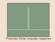
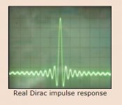
While I am not a speaker expert, I have 30 years experience with digital audio systems. In a digital audio system, the shortest possible transient is a Dirac impulse – i.e. one value followed and preceded by zero values. I have attached the theoretical and real pics of an electrical Dirac pulse from this website: http://tech.juaneda.com/en/articles/dirac.html
Look familiar? That’s a similar result I get measured “acoustically” out of my speakers with the measurement data presented on this thread. Using digital loudspeaker and room correction software, specifically Acourate and linear phase digital FIR correction filters, I can get near perfect “electrical” looking impulse response, but measured acoustically from the speaker. Meaning the transfer function from electrical to acoustic is near perfect. And not just at a single mic position either, as evidenced by the multiple mic position measurement overlay I made yesterday.
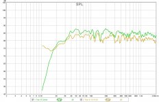
My speakers house a 15” woofer in an oversized 170L sealed cabinet with an f3 of 34 Hz. The digital FIR filters can manipulate any digital signal being passed through it, from DC to Nyquist. Looking at the two measures I made yesterday, one with and one without the digital subsonic filter (in software), with the view of the low end, one can see I am not passing DC as the sweep starts at 10 Hz. See attached of the two measures.
I hope this explains it.
Attachments
Mitch
I don't see how your discussion explains anything. An acoustic signal cannot have a DC response, period. If it does then something is wrong. You have not explained either why an acoustic response does not have to be zero or why your impulse response is not zero at DC.
There should not be DC with or without a subsonic filter.
In the two examples that you show one appears to have 30 dB of gain at
Perhaps you and others do not understand what DC means in an FFT sense. If I take an FFT of an impulse then I get several frequencies coming back. The lowest one is the simplest one and that is the DC term or more generally the level of the mean of the data set. This has to be zero if the system is high passed. It is usually easy to see if this is the case just by looking at how often the impulse stays above zero compared to how often it stays below zero. These two have to be the same. The Dirac impulse does have a DC term, which is in fact equal to all other terms in the FFT. If I pass the Dirac impulse through a high pass filter, like a speaker, then the output cannot contain any DC - in short it can never look like the single impulse that went in, it must have equal area above and below zero coming out. Nothing that you have shown thus far appears to meet this fundamental criteria.
There cannot be DC in the output with or without a subsonic filter.
Your data appears to show some 30 dB of gain at 10 Hz. The system seems to be trying to achieve a DC output, which is cannot. This would be a seriously bad situation in a real audio system, 30 dB gain @ 10 Hz. No loudspeaker could survive that. Most likely no amplifier either.
Earl, the measured acoustic impulse response of my speakers accurately matches the electrical impulse response fed into them. I have provided measurements in this thread that show this is the case.
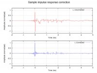
Others have repeated similar. One example is: DRC: Digital Room Correction Scroll down and look at the uncorrected and corrected impulse response, (also attached) and you will see the corrected impulse response is almost identical to the ones I have posted (mine have less preringing ;-) Many before me have already measured and proved that this is the case.
If you do take the time to try Acourate (or other modern) digital correction software and measure the impulse response of your speakers, you will see a very similar impulse response to the one I have posted. No amount of discourse will prove otherwise.
Or when travelling to the West Coast, come visit me and you will see and hear for yourself 🙂
Best regards, Mitch
Attachments
To my eyeballs, this does not appear to be obviously violated by the impulses posted earlier?It is usually easy to see if this is the case just by looking at how often the impulse stays above zero compared to how often it stays below zero. These two have to be the same.
I would be interested to read discussion on whether using FIR filters to stop the phase shift normally corresponding to bass enclosure rolloff is worthwhile and which phase data can be used to do this properly, but it seems completely off topic for this thread..
Perhaps I can answer my own question, but I am still not sure. In a minimum phase system the acoustic response must be a doublet as no DC is allowed and the impulse response of an ideal high pass filter is a doublet. But if the system is not minimum phase as when an FIR correction filter is used, then I am not sure that the impulse response does have to be doublet even though the average of the impulse response over a sufficient data set still must be zero. The non-minimum phase aspect may push this average out over a much longer period of time that the minimum phase aspect would allow (but it still has to happen. This is the only way that I can see an acoustic impulse response that is not initially a doublet.
Earl,
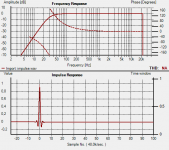
here is the impulse of an "ideal" minimum-phase system (say a perfect fullrange) with a 4th order HP at 30Hz (typical BR box).
You can see that the impulse does not have a major overshoot and is not a doublet.
It still sums to 0 over a long period because the impulse takes a long time to reach 0 again after the overshoot, as can be seen in the zoomed picture.
Attachments

Earl, the measured acoustic impulse response of my speakers accurately matches the electrical impulse response fed into them.
Best regards, Mitch
That's exactly my point - it shouldn't.
Earl,
here is the impulse of an "ideal" minimum-phase system (say a perfect fullrange) with a 4th order HP at 30Hz (typical BR box).
You can see that the impulse does not have a major overshoot and is not a doublet.
It still sums to 0 over a long period because the impulse takes a long time to reach 0 again after the overshoot, as can be seen in the zoomed picture.
Thanks for posting that. I will have to try this myself. I never see a single pulse in any speaker that I have tested.
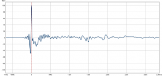
It is possible to have an impulse response that looks close to the bandwidth-limited dirac. This is the ir measured at lp from both speakers, in a very normal room.
How can this be? Phase is within reasonable limits in the upper fr range, remember, what one sees in a ir is mostly what happens at higher frequencies.
This ir also shows that the overall level integrates to 0, i.e. no DC, as it is from a normal speaker with no processing applied for phase correction.
With a IIR corrected response it is not obvious to see the DC because what you look at is a short time (<1ms) compared to the speakers total response, and it is also possible to get a ir that looks very close to ideal, as shown by mitchcba.
Attachments
Its hard to argue with Pos post, with one caveat. What happens if there is a HF rolloff, as will always occur in real life? Your top end is a brick wall. That can't happen in reality. And what about a slower -12 dB / oct fall at a higher frequency - more like what I always see.
But I will admit that it could be hard to see the zero Hz long term average for a system that was flat to 30 Hz when looking at a short piece of the impulse. Not really something that I have ever dealt with.
But I will admit that it could be hard to see the zero Hz long term average for a system that was flat to 30 Hz when looking at a short piece of the impulse. Not really something that I have ever dealt with.
... And what about a slower -12 dB / oct fall at a higher frequency - more like what I always see.
...
Earl,
I have set a HF falloff dialed in as shown above in post 235. My preferred house curve at the LP has this rather large falloff compared to most others. The impact on the SR is as expected. The vertical rise does not continue to a sharp peak because the TW level is relatively low. The level of the midrange is higher so the SR flattops or even rolls up a little more before it falling off normally.
If the TW level is boosted to to flatted out the FR then the normal straight rise to a sharp peak is restored. I have confirmed this with trial measurements.
Perhaps I can answer my own question, but I am still not sure. In a minimum phase system the acoustic response must be a doublet as no DC is allowed and the impulse response of an ideal high pass filter is a doublet. But if the system is not minimum phase as when an FIR correction filter is used, then I am not sure that the impulse response does have to be doublet even though the average of the impulse response over a sufficient data set still must be zero. The non-minimum phase aspect may push this average out over a much longer period of time that the minimum phase aspect would allow (but it still has to happen. This is the only way that I can see an acoustic impulse response that is not initially a doublet.
But I would question the desirability of using this much excess group delay in a correction filter. I know of no circumstances where excess group delay is a good thing and I know of many cases where it is a bad thing.
If you integrate the corrected impulse responses over a long period and they don't average to zero then something is wrong. If they do then they could be correct, but that still is not guaranteed.
Your not looking at this correctly from information/energy standpoint. Energy in equals energy out.
It isn't about minimum phase, but more at causal energy distribution input to filter, and energy distribution output of the filter.
Let energy in be one unit, easily represented as setting a single sample of sampled system to normalized value of one. Sum of all samples in output then is equal to one.
This holds true for both FIR and IIR filters. FIR filter sums to one in discrete interval of filters defined length. IIR filter converges to one at infinity. With IIR filter in audio applications, sample values converge into noise floor of system long before this point, conveniently allowing for truncation.
Single IIR high pass filter has maximal value at first output sample, and FFT window is set to this point and time here may be referenced as t=0. For FIR filter, peak value occurs at midpoint of filter response and filter is symmetric about this point. FFT window set at this point and reference as t=0 results in filter as having response starting at negative time point.
With IIR low pass filter, peak response occurs after start of output signal.
Only first order IIR filter is minimum phase, as least amount of phase rotation occurs across bandwidth. Sum of 1st order high pass with corresponding 1st order low pass filter returns Dirac function, with flat phase response and flat spectrum.
Mitch
I don't see how your discussion explains anything. An acoustic signal cannot have a DC response, period. If it does then something is wrong. You have not explained either why an acoustic response does not have to be zero or why your impulse response is not zero at DC.
There should not be DC with or without a subsonic filter.
In the two examples that you show one appears to have 30 dB of gain at
Perhaps you and others do not understand what DC means in an FFT sense. If I take an FFT of an impulse then I get several frequencies coming back. The lowest one is the simplest one and that is the DC term or more generally the level of the mean of the data set. This has to be zero if the system is high passed. It is usually easy to see if this is the case just by looking at how often the impulse stays above zero compared to how often it stays below zero. These two have to be the same. The Dirac impulse does have a DC term, which is in fact equal to all other terms in the FFT. If I pass the Dirac impulse through a high pass filter, like a speaker, then the output cannot contain any DC - in short it can never look like the single impulse that went in, it must have equal area above and below zero coming out. Nothing that you have shown thus far appears to meet this fundamental criteria.
There cannot be DC in the output with or without a subsonic filter.
Your data appears to show some 30 dB of gain at 10 Hz. The system seems to be trying to achieve a DC output, which is cannot. This would be a seriously bad situation in a real audio system, 30 dB gain @ 10 Hz. No loudspeaker could survive that. Most likely no amplifier either.
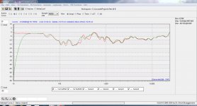
Earl, attached is an amplitude chart of the two digital correction filters used in the two acoustic measurements I took. As mentioned before, I took one acoustic measurement without a 15 Hz subsonic filter in the digital correction filter - that's the red curve. Theoretically, the red curve will allow DC to pass, but there is no source material with DC content. The red curve goes with charts at post 244
There is the +30 dB discrepancy @ 10 Hz between the two correction filters, which explains the 30 dB @ 10 Hz difference between the two measured acoustic responses. The correction filters are normalized to 0 dB, there is no filter boosting.
The green curve belongs to the charts in post 252 and REW measurement file in post 254 which is an acoustic measurement made through this audio chain: REW output->JRiver ASIO line input->64 bit Convolution engine (3-way stereo XO, time alignment, and room correction linear phase FIR filter) JRiver Digital volume-->Lynx Hilo DAC->6 amps->speakers->measurement mic->mic preamp->Lynx Hilo ADC->REW input.
Why I use linear phase filters: Thoughts about crossovers (PDF)
Attachments
Yes, a loudspeaker can't behave like shown by itself.
What Mitch is showing is a pre-distorted signal + native loudspeaker response, yielding a flat phase with flat frequency response. (not to DC, filter delay should be then infinite?)
Does it matter? I think yes, it is desirable to have 0 phase rotation of the harmonics, Griesinger showed a reason why. It all comes down to separating individual sound-streams in a 'busy' environment - coctail-party-effect. This is most effective when the harmonics have the same time-delay, so that the waveform doesn't get smeared.
Daniel
I think that it is true that a loudspeaker by itself can't have a single peak, but the electronics changes that. I can buy that now.
The phase needs to have constant group delay from 700 - 7 kHz as Griesinger says, If the spectrum is flat and the system is minimum phase then the phase will be fine.
I think that it is true that a loudspeaker by itself can't have a single peak, but the electronics changes that. I can buy that now.
The phase needs to have constant group delay from 700 - 7 kHz as Griesinger says, If the spectrum is flat and the system is minimum phase then the phase will be fine.
- Status
- Not open for further replies.
- Home
- General Interest
- Room Acoustics & Mods
- Room Correction with PEQ