Hi, I have a rogers Ravensbrook stereo amp here with a blown SDT9201, farnel have the following replacements 2n5886G.
The issue is pre driver T7 is blown too, but I can not read the faded letters on it. Anyone have any idea what this transistor is, metal can type? I have some bd140 /139 which will probably do if I swap the legs in the right orientation
Thanks.
The issue is pre driver T7 is blown too, but I can not read the faded letters on it. Anyone have any idea what this transistor is, metal can type? I have some bd140 /139 which will probably do if I swap the legs in the right orientation
Thanks.
Do you mean transistor VT7 on the circuit diagram? P.S. I am referring to the Ravensbrook Series II.The issue is pre driver T7 is blown
Sorry its the one in the picture, is that the series 2?
If so then yes it must be VT7 even though it just says T7 on the PCB, the metal head sink clamped around it damaged the lettering. I can not seem to find a schematic with the part number on it.
Thanks for replying
If so then yes it must be VT7 even though it just says T7 on the PCB, the metal head sink clamped around it damaged the lettering. I can not seem to find a schematic with the part number on it.
Thanks for replying
Attachments
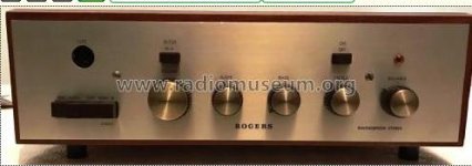
Looks like a Series I because no headphone socket
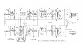
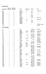
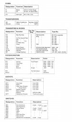
I attach the Series II parts list and circuit for your perusal.
The VT7 driver is listed as a pnp silicon ZN 2905A - I hope this may be of help.
I attach the Series II parts list and circuit for your perusal.
The VT7 driver is listed as a pnp silicon ZN 2905A - I hope this may be of help.
Attachments
Last edited:
Actually, I think that circuit annotation should say Series III, as that is when the headphone output was added and the output power was increased from 15W to 20W.
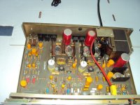
Great thanks so much, that picture of the inside looks the same what I have, and yes no headphone output. I will see if I can find a suitable transistor replacement, I have a few bd140's left from repairing a leak stereo 30 plus / or wharfedale linton, I will check if they match.For reference, the heat sinked driver transistors can clearly be seen directly below the bifilar transformers in the attached image.
Let us know how you get on - I've got a Series III still running in unrenovated condition - may get in and about it one day!
Those are quadrifilar wound transformers by the way!
Those are quadrifilar wound transformers by the way!
I will indeed, it will be in a few weeks time when I get to it. I will have to figure out how to set up the bias as well on this, I see four potentiometers, hopefully I can find something online about it. If you have any info on this it would be a good start.
Regards.
Regards.
I've found information in this link Rogers Ravensbrook Series 3 Amplifier - UK Vintage Radio Repair and Restoration Discussion Forum which states that the driver transistors are PNP BD518 and are replaceable by BD140 with a different lead orientation.(see posts #7 and #11).
Yes, you need to measure the voltage across the 0.47ohm emitter resistors then check the DC offset across the speaker terminals with a dummy load connected.I guess I need to measure voltage across R61, but would a good start be 10mV ?
Around 12mV in each case may be a good start. Will get back if I can find exact specs.
Last edited:
Hi,
Just following up on this as I finally got around to ordering replacement parts, I installed 2 new 2n3055H output transistors, a new bd140 with the leads in correct slots. The BC107's measured fine on both channels so these are not blown. I will power up with a lamp tester in the next few days.
Just so I got this correct,
RP2 To set the bias and measure the voltage across R61 and set it to 10mV on both channels.
Using RP3 to set the dc off set, since this has audio output coupling capacitor, do I measure the voltage before or after the capacitor from the speaker output terminal? And are you saying 12mv is ok for this? Measured from ground to the output signal, set to mV on the DM, with a dummy load on the output. (between 4 - 8 ohm I presume) Just want to make sure, thanks
There are four bias setting preset resistors, two times RP3/RP4, one for each output transistor.
Set the bias to, say, 12mv (I can't find the exact figure) across each 0.47 ohm emitter resistor by adjusting each RP3/RP4 pair.
Set the bias first then measure the dc offset (which you want to be as low as possible, say < 20mV). The dc offset is adjusted by tweaking the bias setting presets. It's a fiddly process which is not helped if the presets are in a bad condition!
The dc offset is measured across the speaker output terminals with dummy load (6 to 8 ohm) connected.
Am I making sense?
Since this is a single rail cap coupled amp, measure in front of the cap and adjust for 1/2 of the b+ rail.
Hi,
Just an update on this encase anyone else needs this info, I got it running, the BD140 as pre drivers and the 2n3055H for output transistors both available from Farnell work very well. I have set up the bias across the four output resistors and its remaining very stable, trim pots are in good order. I cleaned all the controls with a small drop of super 10 switch cleaner. The only issue now I have a small bit of hiss on one channel, its not the source or speakers. I thought it might be tr5 near the balance control as placing my homemade audio listening prob on the metal case this transistor was noisy compared to the other channel, but its not the transistor, I replaced the four electrolytic's around it, but no joy. I tested the ESR on all the larger red caps and the smaller golden axial caps and all are good. I will do some more probing around. The hiss is only there or audible when the volume is way down, but the amp sounds really good, Not surprised. I have a similar vintage R.S.C super 3 & leak stereo 30 plus both recapped and they also sounds great, with efficient speakers they work well
Just an update on this encase anyone else needs this info, I got it running, the BD140 as pre drivers and the 2n3055H for output transistors both available from Farnell work very well. I have set up the bias across the four output resistors and its remaining very stable, trim pots are in good order. I cleaned all the controls with a small drop of super 10 switch cleaner. The only issue now I have a small bit of hiss on one channel, its not the source or speakers. I thought it might be tr5 near the balance control as placing my homemade audio listening prob on the metal case this transistor was noisy compared to the other channel, but its not the transistor, I replaced the four electrolytic's around it, but no joy. I tested the ESR on all the larger red caps and the smaller golden axial caps and all are good. I will do some more probing around. The hiss is only there or audible when the volume is way down, but the amp sounds really good, Not surprised. I have a similar vintage R.S.C super 3 & leak stereo 30 plus both recapped and they also sounds great, with efficient speakers they work well
Thanks for the update! I haven't had to carry out this precedure on my Ravensbrook, so I value any information you can supply.
Did you manage to stabilise the bias at 12mV? What about the dc offset? Were you able to adjust and measure it? If so, by which method?
Hope you get to the bottom of the hiss problem. Let us know if you find a solution. Is the hiss present before the amp warms up, or does in develop thereafter?
Thanks for your time! Will check back later.
No problem, The noise is there all the time, from cold and hot, I have done some more probing, the noise is already present at c21, I listened to the transistor metal case at Tr4 and again one was noisy replaced the BC107b but still no joy, Tr3 on both channels is quite, so getting there, will take another look later tonight. Something between TR3 and TR4.
For the bias I just set the voltage across the four resistors to 12mV, I measured the DC off set at the speaker terminals with 8ohm (old test speakers) connected, and one channel is 2mV and the other 6mV I guess this is ok as we want this as low as possible right?
Regards,
Jer.
For the bias I just set the voltage across the four resistors to 12mV, I measured the DC off set at the speaker terminals with 8ohm (old test speakers) connected, and one channel is 2mV and the other 6mV I guess this is ok as we want this as low as possible right?
Regards,
Jer.
- Home
- Amplifiers
- Solid State
- Rogers Ravensbrook stereo