Ok back to basics for a second so i dont blow anything up that I dont want to replace. I just want to confirm; Q1 is an 2SA1038 PNP transistor. Leg 1 is the emitter, Leg 2 is the collector, and Leg 3 is the base? You think it is safe for me to short Legs 1 and 3?
Datasheet
http://pdf1.alldatasheet.com/datasheet-pdf/view/83333/ROHM/2SA1038S.html
It looks like C5 is connected directly to legs 1 & 3 and has posibly been replaced at one point.
Datasheet
http://pdf1.alldatasheet.com/datasheet-pdf/view/83333/ROHM/2SA1038S.html
It looks like C5 is connected directly to legs 1 & 3 and has posibly been replaced at one point.
Last edited:
OK, I felt confident enough after posting that and looking at the datasheet for a bit. Shorting Legs 1 & 3 allowed the amp to power up sucessfully; but removing the bridge while powered on throws the amp into protect mode. I tested C5 off the PCB and its good.
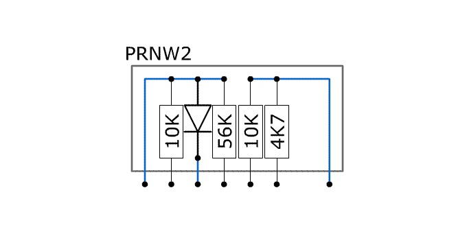
THis would seem to indicate that there is a problem in the PRNW2 module. There are only 4 or 5 resistors in it. When I get back to the other computer, I'll post the values. If you could get a schematic from Mr. Mantz for this amp, it would speed things up a bit.
Is 0.3vDC insignificant across the speaker terminals when Q1 is off the PCB? If 0.3vDC is a problem then perhaps it is not the PRNW2 module. If 0.3vDC is OK then you are probably right about a problem with PRNW2 or similar.
The break between the 33k resistors and the main board disconnected the DC offset protection from the protection circuit.
I'm not sure what the exact threshold is (and it probably varies a bit) but the protection circuit would need to see more than 1v to shut down the amp.
I'm not sure what the exact threshold is (and it probably varies a bit) but the protection circuit would need to see more than 1v to shut down the amp.
I pulled the PRNW2 off the pcb and it checks out. All resitors and the diode are within tollerance and are not leaking to inappropriate pins.
Leaving the PRNW2 off the PCB indeed does allow the amp to power up - Not in protection.
Do you think there might be more leaking components inside the ANW7s? I still have the 8k2 resistors jumping the outer two detached pins on the PCB of each module.
Do you think there might be more leaking components inside the ANW7s? I still have the 8k2 resistors jumping the outer two detached pins on the PCB of each module.
Last edited:
On the LM358 (And with the PRNW2 off the PCB). Should I be seeing these voltage readings?
LM358; IC3
1: 0.008
2: 5.5
3: 0.008
4: 0
5: 5.5
6: 9.7
7: 0.008
8: 10.98
With the PRNW2 back in the PCB and the amp in protection mode the LM358 measures this:
LM358; IC3
1: 9.4
2: 5.5
3: 11
4: 0
5: 5.5
6: 9.7
7: 0.008
8: 11.08
LM358; IC3
1: 0.008
2: 5.5
3: 0.008
4: 0
5: 5.5
6: 9.7
7: 0.008
8: 10.98
With the PRNW2 back in the PCB and the amp in protection mode the LM358 measures this:
LM358; IC3
1: 9.4
2: 5.5
3: 11
4: 0
5: 5.5
6: 9.7
7: 0.008
8: 11.08
That's normal.
When you checked Q1 for leakage, did you have approximately 3M ohms when forward biasing the junction (B-E and B-C) and OL when you reversed the probes?
Did the meter read OL no matter the probe position when they were on the emitter and collector?
All of this would be with the meter set to ohms.
When you checked Q1 for leakage, did you have approximately 3M ohms when forward biasing the junction (B-E and B-C) and OL when you reversed the probes?
Did the meter read OL no matter the probe position when they were on the emitter and collector?
All of this would be with the meter set to ohms.
The only two readings I get off Q1 iswhen I reference COM of the meter to Leg 3. Testing from Leg 3 to Legs 1 or 2 gives 4M ohms. There is no leakage; IE in reverse and all other orientations the meter shows OL.
B-E (Red on E) gives me 4M ohms.
B-E (Red on B) is OL
B-C (Red on C) gives me 4M ohms.
B-C (Red on B) is OL
E-C in either direction gives OL
From this, Q1 has good mesurment and no leakage.
B-E (Red on E) gives me 4M ohms.
B-E (Red on B) is OL
B-C (Red on C) gives me 4M ohms.
B-C (Red on B) is OL
E-C in either direction gives OL
From this, Q1 has good mesurment and no leakage.
When you removed Q113 and Q213, did it still go into protect?
I just removed Q113 and Q213 just to make sure and the amp still turns on in protection mode. Thats with all other circuits in place.
I can do that. Just did it actually with sergical scissors. I verified with DVM that diode leg is detached; and of course I can put it back with a little solder when done.
Unfortunately the amp still goes right in to protection mode.
Last edited:
That disconnects the module from the rest of the over-current circuit so it appears that the module may have problems. Removing Q1/2 disconnected the module from the DC offset circuit and the amp still went into protect. Those are the only two protection circuits driving the module.
It's a simple circuit so I'd suggest that you reproduce it using discrete parts.
It's a simple circuit so I'd suggest that you reproduce it using discrete parts.
- Status
- Not open for further replies.
- Home
- General Interest
- Car Audio
- Rodek 275i (ZED Audio) amp