There is no such thing as copper traces on a PCB. Just a big pile of resistors, capacitors and inductors all trying to fool you. Sometimes you can play along with the joke and get on fine, other times they'll turn around and bite you. 😀
It was a little sarcastic overstatement to indicate very high frequency. Specification calls for 22.5 GHz if I am not mistaken. Sorry if I confused you, but yes I think you understand the statement, fluorescent lamps, motors, light dimmers, cellular phones are all sources of interference. A PCB layout can make a huge difference.What do you mean by daylight? Is it fluorescent lamp?
Power tracks running in parallel with sensitive signal track can induce noise because the two inductors act as a transformer. There are many small things to look out for to avoid if possible, there is no magic formula, it is a learning curve. I think your previous board is as good as it can be, you have followed all the guidelines.
Last edited:
The previous one is better. With this current layout you will modulate the left hand side power line to the driver circuitry which is very audible and definitely measurable.Is this good? I still prefer the previous one though...
What I mean is that the power transistor connected to the left hand power trace will pull the voltage down to the low current circuits connected after it each time it draws current.
D
Deleted member 148505
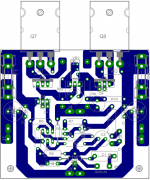
This is my favorite layout, it uses no jumpers(except for a wirelink in speaker zobel ground), and all the components are on board...
Then that is the one you build and be proud of it

Decoupling Caps should be after the fuses not before. Fuses and holders have resistance. I don't like fuses on power amp boards. I always build them as part of the power supply not the amplifier, which is where they should be.
This is my favorite layout, it uses no jumpers(except for a wirelink in speaker zobel ground), and all the components are on board...
i like it, you could place the decuopling caps of the supply lines after the fuseholders, but you've made great improvements over the first design.
build it, and be proud
P3 PCB
I designed and made the Elliot P3... not sure if it was the 'A' variant.
It used the TIP2955/3055, and i paralleled up the OP stage (suggested mod) as my HNC EEE project.
I could dig out the layout....but others are far more skilled in PCB design I feel.
I tried to keep links to a minimum, tried to keep signal away from PSU.
PSU itself was off board, as was the fuses. Also beefed up the OP tracks from drivers, and fed short leads to each OP transistor.
It wasnt small, i got it on to a Euro board easily, and it couldve been alot smaller, but I was just going for a 'make it work' approach.
Noise floor wasnt all that great, but I reckon thats due to me forgetting to include the PSU zobel/diode circuit.
D
Deleted member 148505
Thanks, I'll post scope traces, and thd measurements when I'm finished building it...
@John Bali
It's your turn now 🙂
@John Bali
It's your turn now 🙂
Fuses and holders have resistance. I don't like fuses on power amp boards
can be used Polyswitch's. Are solder in the pcb and don't need change before a fail: restar automatically.
RXEF300 - TE CONNECTIVITY / RAYCHEM - POLYSWITCH, RADIAL, 3A | Farnell España
An externally hosted image should be here but it was not working when we last tested it.
Polyswitches
Unfortunately, the resistance of these polyswitches will make any fuse resistance look insignificant. However, as a cheap protection for utility amps, instrument amps etc. they are a great way to get rid of output relays.can be used Polyswitch's. Are solder in the pcb and don't need change before a fail: restar automatically.....
Good idea, especially when testingcan be used Polyswitch's. Are solder in the pcb and don't need change before a fail: restar automatically.
Last edited:
The polyswitch that I include the link have a Holding Current of 3A until 72V. Perhaps best search one of 3A of Tripping Current for use in the P3A.
The resistance are 0.07 Ohm, not too much.
The resistance are 0.07 Ohm, not too much.
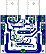
Here's my new layout for p3a
Added base stoppers for drivers and output transistors and added VBE CE bypass cap
hello, I see you changed the transistor "bias", I wanted to know if I can use this circuit to "+ - 42VCC"
regards 🙂
@luisitolco22, if you check rod's site on this amp he says 42volts is max no highter as the amp is not designed to handle it..
The short answer is no for using 2N3055/2955, BD139/40 or any such common, low voltage (Vceo) transistors. Experience shows that 40V rails with small transformers (and allowing for unknown line voltage fluctuation) that drop voltage under load are OK but anything over 130VA or higher than 40V rails is a sure-fire smoke maker. The transformer should be a small 28+28VAC max. or a larger 25+25VAC type is just as good.... I wanted to know if I can use this circuit to "+ - 42VCC"......
The better solution is to use the improved VAS, driver and output transistors as discussed in Sakis's P3a threads if you want higher power, which may be possible with well chosen substitute semis. The original project is copyright to Rod Elliott at the ESP website and details are all there, including purchase of PCBs with full documentation, if you haven't already seen it. 60-80W Power Amplifier
Last edited:
hi all, of course I appreciate your opinions, I forget to specify the transistors that I will use with this circuit is more, the high school assembly in the original version, using the power transistors "mjl21193" and "mjl21194"
the "BD139" and "BD140" as drivers
"BC546" at the input of the differential pair and a current generator and to adjust the quiescent current.
my idea is to build the circuit with the modifications made by "jlester87" using transistors as drivers' mje15032 "and" mje15033 ".
replacing one of the "BC546" by a "BD139" for adjusting the quiescent current.
I will use a "+ - 42V" I will have a problem?
Greetings and sorry for being annoying.
BD139 and BD140 have a Vceo of 80V. On 42V supplies they might see a maximum of 84V across them. That is a risk. They may work fine but you would be running the transistors over their maximum rated voltage.
Any of the MJE1503x series will make good driver transistors.
Any of the MJE1503x series will make good driver transistors.
No need to ask - parts effectively the same as you nominate are already specified on ESP schematic for +/- 42V rails.my idea is to build the circuit with the modifications made by "jlester87" using transistors as drivers' mje15032 "and" mje15033 ".
replacing one of the "BC546" by a "BD139" for adjusting the quiescent current.
I will use a "+ - 42V" I will have a problem?
Jlester87 is presenting just his PCB version for the original schematic. If you wish to use BD139 as a Vbe multiplier, that is fine too, as it is not critical. Beware that this is a CFP design and so it does not sense the output transistors - it senses the driver transistors which don't strictly need to be in direct contact so a TO92 type is fine but some guys like to bolt everything together too.
- Home
- Amplifiers
- Solid State
- Rod Elliot P3A Layout - Critics