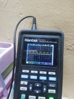
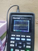
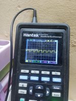
Well Perry, Sean I think I need help, the amplifier shows a perfect square wave without the mosfet, install one on each side and just install the mosfet the signal goes off completely and I checked the drive transistors the resistor diodes and nothing measures bad even I have already changed the lm5110 and I also not only get a square wave at the entrance of the lm5110 with the mosfet on and also the blue led stays on but nevertheless the yellow of protection is blinking constantly and the consumption is not greater than 2 amps in a few words the class d is not activating, any idea where to keep looking.
Do you have the jumper on the class D driver board?
No, I removed it as soon as I installed the rectifiers
What if you load the output with 0.01uF capacitors (one per bank, 4 banks) instead of the outputs?
I have not done this, but when I return home at night I will do it, should the capacitor be polarized and at what points should I connect it exactly for this test drain gate and source?
Did you measure the resistance from the gate to the other legs of the FETs after removing them?
No, I removed the fet and tested them with my esr meter, I will measure the resistance in the circuit and send you the results.
Thank you
Sorry I misunderstood I thought you wanted me to measure the resistance on the pins of the board. I understand now that you want me to measure the resistance of the fet. What value should I find right and what should be bad? only to better understand the test and for knowledge since I always measure the diode scale in the fet and in the Esr meter
Good morning Perry,
In spite of my best efforts, I can't get the amplifier to swing with the mosfet on, it's like I'm protecting myself from a problem on the output but it only happens when I put the mosfet on, you think I have problems with the feedback I've been looking at the diagram that you I sent but I still don't get an answer to see if you give me more ideas please and thank you
In spite of my best efforts, I can't get the amplifier to swing with the mosfet on, it's like I'm protecting myself from a problem on the output but it only happens when I put the mosfet on, you think I have problems with the feedback I've been looking at the diagram that you I sent but I still don't get an answer to see if you give me more ideas please and thank you
- Status
- This old topic is closed. If you want to reopen this topic, contact a moderator using the "Report Post" button.
- Home
- General Interest
- Car Audio
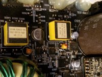
- Rockford T2500 - 1BD