Yes those voltages are with remote applied.
Without remote and amp still powered up:
1= 3.02v
2= 1.71v
3= 17.00v
4= 0v
5= 4.96v
6= 4.96v
7= 0.00
8= 2.40v
9= 2.70v
10= 1.40v
11= 1.40v
12= 0.0
13= Goes up and down between 0.66v to 1.11v
14= 1.2v
I just noticed the thermal light lights up along with the power and protect. In both scenarios with and without remote.
Something is wrong with the numbers above. According to the diagram, pins 1 and 2 are directly connected.
Are pins 10 and 11 shorted? 10 should be lower.
Are pins 10 and 11 shorted? 10 should be lower.
Sorry my mistake I had it written correctly, checked it once more before posting:
1= 3.02v
2= 3.08v
3= 17.00v
4= 0v
5= 4.96v
6= 4.96v
7= 0.00
8= 3.20v
9= 2.70v
10= 0v
11= 1.40v
12= 0.0
13= Goes up and down between 0.66v to 1.11v
14= 1.2v
1= 3.02v
2= 3.08v
3= 17.00v
4= 0v
5= 4.96v
6= 4.96v
7= 0.00
8= 3.20v
9= 2.70v
10= 0v
11= 1.40v
12= 0.0
13= Goes up and down between 0.66v to 1.11v
14= 1.2v
Arite, 95% of the demons were beat out when I replaced the 339. Remote worked again, thermal light went out, came out of protect. I stopped here for today, I have some work to complete on the thermistors as I had these jumpered to the board (seemingly I don’t have the originals on the MESHA thermal pads) and a couple other ends to tie up due to the troubleshooting process, hopefully I can have this done tomorrow and I get to test it out. Will let you know how it goes.
Arite, I got the back together powered up and did some audio tracing with the scope as I didn’t have audio on the output. I replaced all op amps TL072s, in the pre amp section and I got some progress. I have audio at the output with the master/slave switch set to slave. With the switch in either master or single I don’t get any audio output.
With no signal connected I have a 25hz signal at the output.
I rechecked the PWM A+B and the triangle wave, all are present.
I cleaned the switches but this didn’t help.
Any of you guys ever saw this? And/or could help me proceed?
With no signal connected I have a 25hz signal at the output.
I rechecked the PWM A+B and the triangle wave, all are present.
I cleaned the switches but this didn’t help.
Any of you guys ever saw this? And/or could help me proceed?
How can that be? The switch output goes through the same path, beyond the switch, regardless of mode.
You have me doubting myself all the time. Seems I have a faulty SW100 and RV101, jumpered across the switch and wired in an external pot, no DC, got audio out at the outputs, amp idles at roughly 3.25A. Gonna try sourcing these. Thanks again for the help.
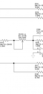
That's odd. This is a 'state variable' filter. Most use 3 variable resistors. I'm not familiar enough with them to know if the 4th (higher rolloff) is a different value. If you ask on the following forum, maybe they could tell you definitively.
https://www.diyaudio.com/forums/analog-line-level/
What do the sections in the one you have read?
https://www.diyaudio.com/forums/analog-line-level/
What do the sections in the one you have read?
- Home
- General Interest
- Car Audio
- Rockford Fosgate T40001BD