Hi guys, I got this amp in with blown PS and output FETs, I worked through the PS and got it running:119v. I then moved across to the audio side and replaced all four drive circuit components along with the two 5110s. I've powered up the amp with only four output FETs installed (Q414, Q417,Q426, Q434). I'm getting (attached pics):
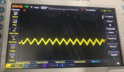
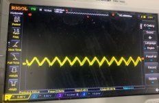
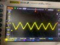
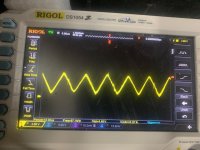
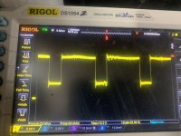
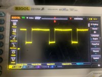
- a clean triangle wave on pin 5 - U301, 302.
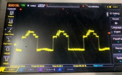
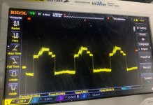
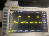
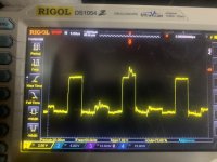
- a fuzzy square wave on both toggle A and B.
I found the 10v gate drive voltage on the 5110 (pins 3 and 6), to be 3.6v. Without the audio board connected, I'm getting the 10v gate drive voltage at the emitter of Q45 and at the grey ribbon cable. With the audio board connected it drops back to 3.6v. I worked my way through the drive components a second time looking for shorts and leaks but nothing, I replaced both 5110s again, same results. I looked at the LM317 and replaced as a precaution, again the 10v gate drive drops to 3.6 when the audio board is connected. ?
All other voltages (5v ref, 6v, 15v) are present. Is my 74hc74 bad?
- a clean triangle wave on pin 5 - U301, 302.
- a fuzzy square wave on both toggle A and B.
I found the 10v gate drive voltage on the 5110 (pins 3 and 6), to be 3.6v. Without the audio board connected, I'm getting the 10v gate drive voltage at the emitter of Q45 and at the grey ribbon cable. With the audio board connected it drops back to 3.6v. I worked my way through the drive components a second time looking for shorts and leaks but nothing, I replaced both 5110s again, same results. I looked at the LM317 and replaced as a precaution, again the 10v gate drive drops to 3.6 when the audio board is connected. ?
All other voltages (5v ref, 6v, 15v) are present. Is my 74hc74 bad?
Attachments
What gate voltage drive drops when the audio board is connected?
Most Rockford class D amps are easier to troubleshoot without rail voltage. Removing the red and blue wires will disconnect rail from the outputs. Confirm that the voltage at the rail caps is not more than their rated voltage after disconnecting the red/blue wires.
Most Rockford class D amps are easier to troubleshoot without rail voltage. Removing the red and blue wires will disconnect rail from the outputs. Confirm that the voltage at the rail caps is not more than their rated voltage after disconnecting the red/blue wires.
What gate voltage drive drops when the audio board is connected?
There's a 10V gate drive voltage, pins 6 on the LM5110 its reading 3.6v.
Most Rockford class D amps are easier to troubleshoot without rail voltage. Removing the red and blue wires will disconnect rail from the outputs. Confirm that the voltage at the rail caps is not more than their rated voltage after disconnecting the red/blue wires.
With the red and blue wires removed they measure 142.2v.
I removed both 5110s and Q402, Q403, Q408, Q409 out the drive circuit. I powered up the amp without blue and red wires connected (both ribbon cables and white wire connected, as you stated above Perry). Signal looked a lot cleaner coming into both solder pads 2 and 4 (of the two 5110s). Voltage on solder pad 6 measured 11.02v.
I soldered in one (new)5110 and powered up again, voltage on pin 6 fell to 5.15v. Signal waveform on pins 2 and 4 went back to weaker and fuzzier as before.
I was hoping to "unload" the drive transformer to see where the problem lies, is the GTD faulty? I measured the resistance on solder pads (5110 removed) 5 and 7 for both transformers (primary) and they measured 0.4 ohms. I'm hoping the transformers are still functional.
I stopped at the last point there today (#8), I have most of the drive circuitry out the board as I'm suspecting something is pulling the 10v on pin 6 of the 5110s down to 3.6v.
I thought I mentioned this in the initial post but the 5110s are getting a bit hot (cant touch) along with Q27 (317). The voltage drops to 3.6v on pin 6.
I thought I mentioned this in the initial post but the 5110s are getting a bit hot (cant touch) along with Q27 (317). The voltage drops to 3.6v on pin 6.
If the ICs are getting hot and pulling down the 10v supply, lift the output terminals and see if the drive signal is passing through the IC.
If it is, the transformer is loading it too heavily. This could be from the transformer being shorted or from a load on the other side of the transformer. The next step would be to reconnect the IC and to disconnect the circuit from the other side of the transformer and check for the signal passing through the transformer.
Do this without rail voltage.
Arite I pulled all eight diodes (D400,401,D402,403,D408,D409,D410,D411). Both 5110s are heating up and the 10v is pulled down again to 3.6. The resistance the transformers secondaries seems consistent around 0.6 ohms. I measured the primary sides previously and they measured 0.3 ohms. I’m guessing the transformers are shorted. Without the diodes installed it’s just the transformer loading the 5110s.
I have all the drive components installed, I removed both transformers, both 5110s run cool, not heating up again. I attached some pics of waveforms at various points, with and without R315 jumpered they look almost identical. it seems both transformers are shot.
From reading various posts I think these are extremely hard to come across, Anyone with details on substitutes or rewinding or winding one?
From reading various posts I think these are extremely hard to come across, Anyone with details on substitutes or rewinding or winding one?
Attachments
Ok folks, I received the replacement transformers and after a long weekend, I managed to install them, had to replace both 5110s again, and I found a defective zener diode D412. After replacing them all, I got carrier triangle waves on U301 and 302, and square waves for both toggle A and B. All appeared alright on the scope, I installed all 20 output FETs. Amp powered up for a few mins, gate drive voltages on both 5110s were verified at 9.96v, all op amps in the audio section had their +\- 14.85v, all op amps in the BD section had their +\- 6v. Amp was shut off for a few hours, when powered up it goes into protect. In addition to this, when I remove the remote power, the amp remains powered up.
I did some voltage checks on U1, listed below. Any ideas as how to proceed?
1= 4.71v
2= 4.70v
3= 17.0v
4= 4.21v
5= 4.96v
6= 4.96v
7= 7.91v
8= 4.98v
9= 3.28v
10= 1.39v
11= 2.08v
12= 0.00v
13= 3.47v
14= 4.19v
I did some voltage checks on U1, listed below. Any ideas as how to proceed?
1= 4.71v
2= 4.70v
3= 17.0v
4= 4.21v
5= 4.96v
6= 4.96v
7= 7.91v
8= 4.98v
9= 3.28v
10= 1.39v
11= 2.08v
12= 0.00v
13= 3.47v
14= 4.19v
- Status
- This old topic is closed. If you want to reopen this topic, contact a moderator using the "Report Post" button.
- Home
- General Interest
- Car Audio
- Rockford Fosgate T40001BD