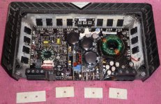
Hi Folks, checking out a Rockford Fosgate T1500-1bd.
It just stopped playing. No protect light, no smoke, no fuses blown. It appears to turn on normally, just no output.
I checked the outputs (IRFP3415) and the supply fets (75344g), all good.
The rails read +32 and -40 at CR1004 and CR1005.
After you turn it off the pos rail runs up to 77volts or so, while the neg rail quickly drops from the -40 to 0.
The low voltage supply seems kind of funny - at the rectifiers (CR1000-CR1003) the output is plus/minus 26.8 volts, with the LM317 reading +14volts and the LM337 -15volts.
The lm337 heatsink seemed to get really hot really fast, and somethings warm on the subboard next to it (left most board)...
Does anyone know what the rails should be?
I have a schema for a Power 2004 T10001bd. Does anybody know if its close?
I have to run out for a minute, but I'll remove the subboard when I get back I guess as there's no access to it for metering, etc.
Also, this amp has aluminum panels instead of the normal thermal boards....?
So, any ideas on where to start?
Attachments
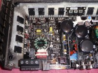
Confirm that the regulator transistors Q2000, 2001, 2010, 2012 have the correct output voltage (-6, +6, +10, +10 respectively).
Check the solder connections on R2035 and make sure that R9 isn't broken from the board.
Check the solder connections on R2035 and make sure that R9 isn't broken from the board.
Also check both 5110 ic's to make sure they are not shorted or leaky.
U2002 and U2000 I believe they are.
U2002 and U2000 I believe they are.
Due to a lack of demand for the tutorial, it's unlikely that I will be doing many more updates. Email me if you any other questions regarding the tutorial.
checking trans Q2000, etc
Okay, on the four transistors:
Q2000 (-6.7)(-22.5)(-6.1)
Q2001 (6.8)(17.8)(6.2)
Q2010 (11.8)(17.8)(11.2)
Q2012 (11.8)(17.8)(11.2)
B+ is 12.0
R2035 and R9 good.
I went through it after measuring and cleaned up a lot of really bad looking (cooked dry) solder.
Confirm that the regulator transistors Q2000, 2001, 2010, 2012 have the correct output voltage (-6, +6, +10, +10 respectively).
Check the solder connections on R2035 and make sure that R9 isn't broken from the board.
Okay, on the four transistors:
Q2000 (-6.7)(-22.5)(-6.1)
Q2001 (6.8)(17.8)(6.2)
Q2010 (11.8)(17.8)(11.2)
Q2012 (11.8)(17.8)(11.2)
B+ is 12.0
R2035 and R9 good.
I went through it after measuring and cleaned up a lot of really bad looking (cooked dry) solder.
You have to measure the rail voltage with the two probes on the center legs of the rectifiers (no probe on ground).
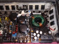
This amp uses metal heat spreaders with an insulating coating. There should be one behind all of the output transistors. Do not let the transistors touch the heatsink.
The diagram that you have may be good enough to give you some idea of what the circuit is but it's not close enough for most components.
Don't remove anything yet.
Do you have an oscilloscope?
How to test 5110 for leakage?
The 5110s are U2000 and U2002,but I couldn't find a datasheet for them. What are they and how should I test them?
Also check both 5110 ic's to make sure they are not shorted or leaky.
U2002 and U2000 I believe they are.
The 5110s are U2000 and U2002,but I couldn't find a datasheet for them. What are they and how should I test them?
Rail voltage
Ok, the rail measurement is about 20. As I apply/remove Remote it pops up to seventy for just a moment then comes down just as fast.
No scope at the moment. I have an old pc I use as a sound card scope, just can't measure DC.
If I feed it some audio, can I rule out the preamp, x-over etc?
What is the function of the left most card?
Imma head over to bcae and brush up on class D.
You have to measure the rail voltage with the two probes on the center legs of the rectifiers (no probe on ground).
Ok, the rail measurement is about 20. As I apply/remove Remote it pops up to seventy for just a moment then comes down just as fast.
This amp uses metal heat spreaders with an insulating coating. There should be one behind all of the output transistors. Do not let the transistors touch the heatsink.
Do you have an oscilloscope?
No scope at the moment. I have an old pc I use as a sound card scope, just can't measure DC.
If I feed it some audio, can I rule out the preamp, x-over etc?
What is the function of the left most card?
Imma head over to bcae and brush up on class D.
In general, soundcard scopes are only good for audio. They can't be used for troubleshooting the class D circuits or the power supplies without a LOT of guesswork.
The card near the SMD regulators is the audio PWM generation circuit.
I think the input to the audio PWM card is one of the two pins at the back end of the card.
Did the amp go into protect mode?
The card near the SMD regulators is the audio PWM generation circuit.
I think the input to the audio PWM card is one of the two pins at the back end of the card.
Did the amp go into protect mode?
Ok, at least I can verify that I'm getting a signal to the pwm card.
Nope no protect mode. Just no audio. Verify tiny power on thump when the supply kicks in.
Seems like the amp part is working, just not getting a signal.
Nope no protect mode. Just no audio. Verify tiny power on thump when the supply kicks in.
Seems like the amp part is working, just not getting a signal.
Post the DC voltage on all pins of both LM5110 ICs.
Pin 1:
Pin 2:
Pin 3:
Pin 4:
Pin 5:
Pin 6:
Pin 7:
Pin 8:
Pin 1:
Pin 2:
Pin 3:
Pin 4:
Pin 5:
Pin 6:
Pin 7:
Pin 8:
Voltages on LM5110s (U2000 and U2002)
U2000
Post the DC voltage on all pins of both LM5110 ICs. :
U2000
- .7
- 1.8
- 0
- 1.8
- 2.2
- 9.5
- 2.2
- 7.3
- .7
- 1.8
- 0
- 1.8
- 2.2
- 9.6
- 2.3
- 7.3
The ICs look OK. Without a scope that can read the higher frequencies, it may be difficult to do any more troubleshooting. Do you have access to a standard scope?
Access to a scope...
I might be able to get some time on one. 2mhz ok, or higher?
In order to rule out any simple stuff, I should be able to detect the audio input signal entering the last card right?
Also, to help with people's future troubleshooting, on that card their are three SMD diodes in sot-23 with a '5D' imprint - I'm pretty sure they are single diodes, not dual - so pin#2 is unused.
Attachments
Tracing audio signal to boards?
Hey, Hope everyone had a good Easter.
Took a look at this amp again this morning jst to verify audio passing through the board. I have audio at rca inputs, but it doesnt seem to enter any of the boards.
Also U1001 (regulator on separate heatsink - pic, seems to be getting really hot.)
Anybody know where I should be seeing audio or what pins of the preamp boards should have it?
Or any comments on the regulator U1001? Does it normally run hot-hot?
Attachments
In post #11, you wrote "Ok, at least I can verify that I'm getting a signal to the pwm card.". Were you verifying that you had audio there or were you saying that that was something that you could do (in a future post)?
Tracing signal...
Have signal on pins 1-3 of the TL072 in U3, no audio on 5-7. Its a little distorted around there, but that could be impedance of my homemade probe. Gets strong and clear at R2 and R104. But can't find it entering the first card.
Are these cards used in other amps that someone might have a schematic to?
If I knew the pinout of the card I could test the rest of the amp by signal injection.
Anybody know if there should be anything in R109, C14 or C15? Just want to make sure they should be empty. Solder looks right, but...
Tracing audio....
Sorry, I was saying that verifying audio was something I could do in the future, yes.
So, I have strong audio by the first TL072 by the RCA's and then really distorted, almost am radio sounding static on one of the last two pins of the farther back set.. If I touch the last pin of the first set, I hear a tiny tick through the speakers. So that may be the input/output path of the card, eh?
I'm getting very low output now, I'm not sure if it was present before, had to 'ear' the speaker. The gain knob doesn't affect what I can hear from the speaker at all, although the frequency knob does - as I lower the frequency knob setting, I can hear more high end hiss.
In post #11, you wrote "Ok, at least I can verify that I'm getting a signal to the pwm card.". Were you verifying that you had audio there or were you saying that that was something that you could do (in a future post)?
Sorry, I was saying that verifying audio was something I could do in the future, yes.
So, I have strong audio by the first TL072 by the RCA's and then really distorted, almost am radio sounding static on one of the last two pins of the farther back set.. If I touch the last pin of the first set, I hear a tiny tick through the speakers. So that may be the input/output path of the card, eh?
I'm getting very low output now, I'm not sure if it was present before, had to 'ear' the speaker. The gain knob doesn't affect what I can hear from the speaker at all, although the frequency knob does - as I lower the frequency knob setting, I can hear more high end hiss.
was the rail voltage right?
Also, I didn't know for sure if the rail voltage was right.
Just checked again, and when I connect the remote it jumps to 67 then when I hear the tick from the speakers (unmuting?) it slides down to around 30. Then it very slowly and wobbly rises back up to 50 or so.
Still waiting for response on using a scope.
- Status
- Not open for further replies.
- Home
- General Interest
- Car Audio
- Rockford Fosgate T1500-1bd - no output, no protect, no smoke