Yes, it's true Perry, but I do not know where to look ...
someone has a complete scheme of this amplifier?
someone has a complete scheme of this amplifier?
PapaZBill may be able to help. This amp is virtually identical to some of the Kicker amps (and JL as well).
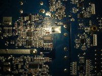
If you can post close up pictures of output drivers and surrounding circuitry so that I can read part numbers,and/or post a list of output fets,power fets,PWM and Output driver IC's
You mentioned the 2045's,I'm wondering if the driver IC's are IRS20957?
The power supply seems to work and something is causing the CSD to shut down the amp. Maybe bad driver or Driver IC, Oscillator or the IC comparator(maybe an LM393)for the CSD circuit. Once I see what parts this amp uses I will be able to guide you through it, but looking at the board it's lay out is very similar to the later Kicker amps using a boost converter and H bridge outputs.
Sent from my HTC Desire 626 using Tapatalk
Last edited:
Thank you very much for your help
I have reviewed several times the readings of all components, both the output of the left, like the right hand, and I have not found significant traces, I suspect (my short understanding ..) must be some component is giving me a false reading.
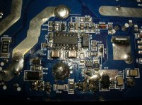
The photograph on the left shows that have replaced IRS20957 and a 2045 on suspicion of them ....
Output FETs have been replaced four IRFB3307
When the amplifier, red LED for three seconds, then a second blue LED, and then fixed red LED is connected.
In the audio output, 40V are measured during the time that matches when the LED turns blue, then is decreasing.
I do not get it...
I'm thinking about replacing again, all semiconductors of the two output parts (diodes, controllers, drivers, FETs ..)
I have reviewed several times the readings of all components, both the output of the left, like the right hand, and I have not found significant traces, I suspect (my short understanding ..) must be some component is giving me a false reading.
The photograph on the left shows that have replaced IRS20957 and a 2045 on suspicion of them ....
Output FETs have been replaced four IRFB3307
When the amplifier, red LED for three seconds, then a second blue LED, and then fixed red LED is connected.
In the audio output, 40V are measured during the time that matches when the LED turns blue, then is decreasing.
I do not get it...
I'm thinking about replacing again, all semiconductors of the two output parts (diodes, controllers, drivers, FETs ..)
Attachments

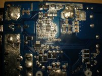
In the second photo there appears to be an open trace between C118,D15 and the right hand lead to output mosfet. Check and repair if necessary.
Check the DC voltage (black probe power ground terminal) around Q110 and post.
Check R125,126,127,128 with an ohmmeter their values and connections to output mosfets.
Check every possible combination around the 2045's and IRS20957's with an ohmmeter
Check all surface mount caps especially the larger ones and check the smaller value resistors such as the 0, 1R0,2R0 and 5R0 ohm resistors.
Do you have a scope?
The open track between C118 and D15, is correct, is not open.
The DC voltage of Q110, (in the short time that I could get to measure it, when the blue LED turns for a second when the red LED on is, the measurement is 0) during the second time measurement is:
Pin 1: 0V to 4V
Pin 2: 4,03V
Pin 3: 1.0V to 2.7V
The resistance values are correct.
2045's and IRS20957's look well.
Proved caps and resistors smaller, and look good.
Yes, I have a scope.
I can not post measurements IRS20957's because I think the amplifier in protected mode (red LED) these measures will not be correct, correct me if I'm wrong ...
OK, we will need to find a why to disable the protection.
There may be an LM339 or similar IC comparator,possibly near the PWM IC (UC3843).
If so there will be a diode (1N4148) that hangs off the output of the LM339 (In the case of Kicker amps, three of the output pins of the LM339 are tied together).
If you remove the diode this may allow the power supply to stabilize and DC voltage and scope measurements are possible.
There may be two more diodes hanging off the outputs,one each connected to the node that shares the two 16 ohm resistors and the output coils. If this is true remove them as well. It's also possible one or both have shorted and may be the reason the amp is toggling in and out of protection.
If you will, clean the board as best you can, so that the IC's and other part numbers are easier to read, and take four more pictures. Each picture should be one quarter of the underside so that if you were to stitch all four together you would have a complete picture of the board.Some overlap is fine and would be helpful. Maybe two more of the topside, splitting the amp in half. The more I'm able to see and read, the better understanding I will have to enable me to help you further.
This may be a process, but I think we can get this amp working, I have a pretty good understanding of the type of amplifier!
Ok, thanks for your interest
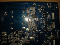
LM339 does not exist, the closest, I think it's a CD4013B, although not near UC3843, well, anyway ...
I hope the pictures are helpful.
Today it's late, tomorrow will remove the diodes to see what happens.
LM339 does not exist, the closest, I think it's a CD4013B, although not near UC3843, well, anyway ...
I hope the pictures are helpful.
Today it's late, tomorrow will remove the diodes to see what happens.
Attachments
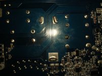
The 4013 is a flip flop,which feeds an integrator circuit.The subsequent sawtooth waveform is the reference for the PWM,comprised of one or both of the 8 pin soic's just to the right of the 4013.
Even though the amp is cutting in and out,monitor the waveform from the 4013 and trace it through the Integrator and follow it as far as you can up to pins 3 of the IRS20957's.This may tell us where to focus our attention.
Sent from my HTC Desire 626 using Tapatalk
Even though the amp is cutting in and out,monitor the waveform from the 4013 and trace it through the Integrator and follow it as far as you can up to pins 3 of the IRS20957's.This may tell us where to focus our attention.
Sent from my HTC Desire 626 using Tapatalk
I am still struggling to read the IC's.Post the part numbers for the following IC's.
U2,U4,U5,U6,U8,U9,U10.... I was not able to find a U7-if it exist post part number and give me an approximation where it is on the board
Also U100,U101,U105 and the PWM chip in the power supply(adjacent to C32), It may be a UC3843, but I want to be sure.
U2,U4,U5,U6,U8,U9,U10.... I was not able to find a U7-if it exist post part number and give me an approximation where it is on the board
Also U100,U101,U105 and the PWM chip in the power supply(adjacent to C32), It may be a UC3843, but I want to be sure.
Yes,
U2: ATTINY13V-10SU
U4: NE5532
U5: NE5532
U6: SL4558D
U7: PC817 (optocoupler, is located on the other side of the board)
U8: SL4558D
U9: SL4558D
U10: SL4558D
U100: NE5532
U101: LM393
U105: CD4013BM
and U1: UC3843B (adjacent to C32)
I tried to do readings with the scope, but do not get it ..
What do you mean 1N4148 diodes? D105 and D106 Are? They are located above and below U105 ...
This amp using a different configuration for protection. The diodes I referred to may not exist.
Okay, If the amp powers up (blue light solid on) and you have rails (80 volts?), maybe it won't be necessary to disable protection, typically with Kicker amps there are some SMD capacitors that fail. Will start with the following:
check ZD102 (12v),ZD105 (24v) and ZD3 (12v) Black probe on power ground. This is the supply for U105 (12v), U101 (36v) and U100 (48v).
If one or more of the zeners do not have the proper voltage's check the capacitors connected in parallel.
check ZD102 (12v),ZD105 (24v) and ZD3 (12v) Black probe on power ground. This is the supply for U105 (12v), U101 (36v) and U100 (48v).
If one or more of the zeners do not have the proper voltage's check the capacitors connected in parallel.
Last edited:
I disconnected C147 and C148 on suspicion of them, I measured with the multimeter, and give 0.1 uf both, but its value based scheme is 4,7uf / 16V ...
Can this be significant?
Can this be significant?
Could be, If they are causing the voltage to drop below 10 volts this will shutdown the IRS20957's. Replace them if you can.
Pin 2 of the IRS20957's is the CSD line just to clarify.
Could be, If they are causing the voltage to drop below 10 volts this will shutdown the IRS20957's. Replace them if you can.
I wonder how many Jack***** have tried to run these things 1 Ohm or less. Lets see, 4 output devices, 2+2/bridged, no way in hell would this thing be reliable at 1Ohm or less.
Anyways... I digress. These amplifiers are not that difficult. The IRS20975, 2045s, output devices, and R127, R128, and a handful of diodes are gonna blow if you loose output devices. Expect that. I think I have seen 1, maybe 2 of these amps now that I recall. I had to fully rebuild the output stages to get them stable again, pretty much. Also the output stages are driven from a separate triangle oscillator, that needs checked. As well as the op-amps/integrator network that feeds the IRS20975. If none of that is stable or clean, itll NEVER work.
As far as the MCU is concerned. if D3 (Pin 7) gets pulled low, it will shut the power supply off. Likewise, if D2 (Pin 5) gets driven high, it will shut the amplifier section off.
Also, there appears to be quite a bit of load on Q1 in the circuitry design, and if that transistor fails the whole amp will malfunction, or appear dead.
The only way the blue LED can come on, is if the +15V is present meaning the power supply converter circuit is running. If that blue LED is on, the power supply is running. Soon as the power supply shuts off, the LED will switch from blue to red. The LEDs are NOT controlled by the processor! they are analog and compare 2 different voltages.
As for advice, I suggest following the schematics because I see a multitude of failure points, and a plethora of different voltages and sources, they ALL need to be checked.
Last edited:
- Status
- Not open for further replies.
- Home
- General Interest
- Car Audio
- Rockford Fosgate Prime R1000-1D