Correction: D2 shuts off the driver ICs and PWM signal, D3 shuts off the voltage to the Op-Amps/Integrators U100/U101 in the amplifier section.
the MCU has no control over the power supply section. it should run unless it goes into over-current, or Remote is removed.
the MCU has no control over the power supply section. it should run unless it goes into over-current, or Remote is removed.
Last edited:
Sorry for delay in answering, but I have a lot of work lately ...
I hope to have less, this week ..
Thank you very much for your contributions mbates14, sure I take the right way to solve this mess.
As more data have, I will continue writing them in this thread
I hope to have less, this week ..
Thank you very much for your contributions mbates14, sure I take the right way to solve this mess.
As more data have, I will continue writing them in this thread
Well, I've replaced a few components:
U102, Q100, Q101, D106, D15, D17
U104, Q103, Q102, D16, D18 and D101
And the result is the same ...
When applied to the amplifier 13V, red led on three seconds, then a second blue LED, and then the power supply of 13V 20A I have to test amplifiers, is protected.
During that second blue LED lights, the voltage rail is activated (40V) then decreases as the electrolytic capacitors are discharged...
I continued doing more tests and measurements ..
In the cathodes of D3, D7 and anodes D4, D5, they are not obtained, + 18V/-18V, only 1.2V ....
I disconnected D3, and connecting the amplifier continues protection, red LED. (This time, fails to ignite even a second blue LED)
I suspect the fault must be connected before the audio output stage ..
I will continue investigating ...
Remove R61-10 ohm and check with an ohmmeter.
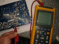
Look at the AC coming out of the secondary windings feeding the D3,D7 & D4,D5. If you use a scope make sure scope ground is connected to the center tap and scope probe to D3,D7 anode side then D4,D5 cathode side. Post a screen shot if you can.
Measure the DC voltage on the cathode side of D12-(Vp1) and post.
Good morning . Could you help me ?
I can not find where any scheme or photos of what and where raspolozhiny transistors on the board.
I can not find where any scheme or photos of what and where raspolozhiny transistors on the board.
Q9, Q8, D12 they belong to the power supply. (IR3077 both transistors, and D12 is 63CTQ100)
Q104 to Q108 are IRFB3307
You should open a new thread, if you want to help better.
Q104 to Q108 are IRFB3307
You should open a new thread, if you want to help better.
Well, well,, this has given a 180-degree ...
The external power supply of 13.8V I was using to test this amplifier does
not test this type of amplifier.(Entering protection too soon..)
There, I had a big mistake ..🙁
Now, I've got another external power supply, although only obtains 12.1V
is more stable and linear.
When connecting the amplifier, red LED two seconds, then blue LED on
permanent rail voltage rises to 67V, In the cathodes of D3, D7
and anodes D4,D5, are obtained +12V and -12V respectively, nothing is
heated and apparently nothing burns, but I have 37V in the speaker output,
They believe that I can connect a speaker without risk of burning
a FET?
In the photo the waveform at the output of the inductor belonging to the audio stage shows.
It seems very linear, is this correct?
Attachments
You should be seeing a squarewave at this point.Try connecting scope ground lead to the power terminal ground. Does the output inductor on the other channel show the same thing?
Is the scope indicating DC voltage?
Check the waveform of Pin 3 of the IRS20957's and measure the DC voltage around 16 pins of the IRS20957's using the power terminal ground for the black probe and post.
Is the scope indicating DC voltage?
Check the waveform of Pin 3 of the IRS20957's and measure the DC voltage around 16 pins of the IRS20957's using the power terminal ground for the black probe and post.
Certainly, you had every reason in the world!
I tried to connect the black cable probe scope, in other ground point of the motherboard (specifically, one carrying a screw attached to the chassis) and see the square waveform in the scope, in the two inductors, as shown in the pic, so I assume that this is correct.
I've ridden the placabase to the chassis, I installed all screws, I connected the amplifier, I measured voltage at the speaker terminals, and interestingly there 0,00V !!
I think that in this type of amplifiers, must be grounding all connected properly to make checks.
I have dared to connect a speaker and audio signal input, and it works!
He has been working for more than an hour without signs of fatigue.
What I have deduced this repair (put aside, all the pieces that have replaced ...) is that this type of amplifier, seems to have a great "dummy" consumption during the first seconds of its start until load capacitors, or until the rail voltage is generated in full, moments later, everything goes smoothly ,, consumption is normal.
It is something, or am I wrong? correct me please ...
Well, I give a lot of thanks, Perry and PapaZbill, which have helped me tremendously, and I am eternally grateful, without his help, I would not have succeeded.
Greetings from Spain, folks!
Attachments
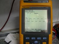
The waveform pictured is what I would expect and the DC voltage should be roughly half the rail due to the nature of the half bridge output circuit. The Driver (IRS20957) switches the rail on and off, leaving an average roughly half the rail voltage.
The output inductor filters out the squarewave leaving only the amplified audio.
Otherwise, all and all I think this was a success and we both learned something!! Glad to help! Cheers from Americas heartland!
The output inductor filters out the squarewave leaving only the amplified audio.
I would say this was the heart of your problem, after fixing whatever was ailing this amp to begin with. The power supply didn't have enough "juice" to overcome any in rush current the amp demanded to bring up the rail and stabilize the amp.What I have deduced this repair (put aside, all the pieces that have replaced ...) is that this type of amplifier, seems to have a great "dummy" consumption during the first seconds of its start until load capacitors, or until the rail voltage is generated in full, moments later, everything goes smoothly ,, consumption is normal.
Otherwise, all and all I think this was a success and we both learned something!! Glad to help! Cheers from Americas heartland!
Hi, I have acquired one of these amps that needs repair. I have been reading through this thread and have noticed from the pictures posted that the underside of the board has a couple variations from what im seeing on mine.
1st thing im seeing is the resistors located at r136 and r137 only has one resistor at a 16 ohm value but then i noticed that further down the board at r135 or(138 cant tell) and r139 it is also missing one 16 ohm resistor. It appears to be a parallel configuration in series so i would think the value would offset the same with the exception of higher wattage capability .I was under the impression that this amp hasn't been worked on before and am at a personal debate of putting the two missing resistors into the circuit. So far all i have found on this amp was the power supply schematics and not the full print.
Also noticed that the power supply section has a variation located at the diode nzd1 on the posted photo. This leads me to believe there were different minor revisions of the R1000.1D.
This is the 1st car amp i decided to take a crack at but i am actually a Servo drive amp and VFD technician. After my long weekend is over i planed to take the amp to work and use my huntron tracker to go through the amp.
Oh yea the amp is flashing protect every few seconds with only power applied no rca and speakers hooked up. Also nothing looks burned or blasted.
- Status
- Not open for further replies.
- Home
- General Interest
- Car Audio
- Rockford Fosgate Prime R1000-1D