It's not absolutely necessary so connect the capacitor across the gate and source pads of the PS FETs, before installing them, and measure the DC voltage across the capacitor.
I still need to see the backs of the FETs that you installed, then removed. If you threw them out, post a photo of the new FETs (top and bottom) before you solder them to the MEHSA insulators.

I can't see anything of use at that resolution. What's important is that the solder flows freely over the entire back of the tab. For some FET finishes, you need to scuff the back of the FET with sandpaper (or similar) and use additional flux. Excuse the quality of the following video (nearly 20 years old) but it shows FETs that took solder readily and some that did not. Properly prepared transistors will take solder like #2. If they take too long to tin, there is a chance that the FET will be damaged.
https://www.bcae1.com/temp/tinningtransistors01.avi
https://www.bcae1.com/temp/tinningtransistors01.avi
thanks, really helpful. im only worried now i cant get mehsa cleaned.
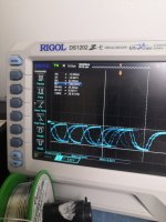
didnt find that capacitor so maybe we gonna scope this thing.
i cant tell if my friend has done any amp stuff so any advice what should we look at
didnt find that capacitor so maybe we gonna scope this thing.
i cant tell if my friend has done any amp stuff so any advice what should we look at
The capacitor is important with the scope, or not.
Do you have any other heat sources? (NOT a propane torch)
Do you have any other heat sources? (NOT a propane torch)
Looks like 10V
Attachments

Last edited:
i was worried about that shape. my friend had larger iron and his helping hand with hot air mehsa board also clean now. pad 4 had 1.6V today
Last edited:
The shape is due to the capacitor. What's important is that is goes near 0v. The drive circuit often fails and won't pull the capacitor back to near 0v. Without the capacitor, it may not be obvious. For Rockford amps of this design, you can also check with the FETs as a load but you don't connect B+ (only remote and ground used). The capacitor without the FETs is universal so you should learn to use it if you plan on doing more repairs.
its not economically viable to keep this amp going, but i love these lil amps. i wish i can fix this permanently.
im gonna slap irf´s to board, any measurements before broken channel fets back in? bias turned down at least
im gonna slap irf´s to board, any measurements before broken channel fets back in? bias turned down at least
Unless you know how to properly test the driver transistors and resistors, there isn't much you can do.
You should (for all FETs freshly installed onto the MEHSA strips) is to measure the gate to the other terminals and confirm that they don't read unexpectedly low in resistance. The FETs can be damaged if too much heat is used and become leaky or shorted.
Setting the bias to the minimum setting is standard practice for all repairs that involve replacing parts in a channel.
amp is turning on but theres that occasional 28v dc
lm339 and tl494 are located side by side,that area heats up pretty warm.
sometimes when i bend the board i can see amp in working condition, it was on couple minute i got it biased 1-2mv, draws 0.8amps that state. when i see draw droppin 0.6 or 0.4amps biases drops.
not very reliable amp
lm339 and tl494 are located side by side,that area heats up pretty warm.
sometimes when i bend the board i can see amp in working condition, it was on couple minute i got it biased 1-2mv, draws 0.8amps that state. when i see draw droppin 0.6 or 0.4amps biases drops.
not very reliable amp
You need to push (with a non-conductive probe) on various points on the board to see if you can find an area or component that makes the fault come and go.
If not, intermittently freeze (component chiller or inverted canned air) and heat various points on the board to see if you can make the fault come and go.
It's not that it's unreliable. It's not fully repaired.
If not, intermittently freeze (component chiller or inverted canned air) and heat various points on the board to see if you can make the fault come and go.
It's not that it's unreliable. It's not fully repaired.
its R23 which heats smokey hot when channel pulls 28v.
i have to pull R6 and R10 out board and measure them, maybe some others as well
i have to pull R6 and R10 out board and measure them, maybe some others as well
- Home
- General Interest
- Car Audio
- Rockford Fosgate 160A2 doesnt power up