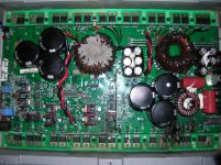
Hello, today I received this amp, I bought on eBay.
I keep thinking, how someone can destroy an amplifier of this form.
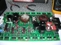
I counted seven mosfet destroyed, burned six resistors, four capacitors swollen, two ceramic pieces are missing, and sure there is more bad parts.
I do not know where to start.
Do not enter my head, how could that happen.
Anybody can explain me?
Tomorrow I'll start to repair it.
I keep thinking, how someone can destroy an amplifier of this form.
I counted seven mosfet destroyed, burned six resistors, four capacitors swollen, two ceramic pieces are missing, and sure there is more bad parts.
I do not know where to start.
Do not enter my head, how could that happen.
Anybody can explain me?
Tomorrow I'll start to repair it.
Attachments

Your in luck, its not the worst. Atleast the entire citcuit board isn't burnted. Damage like this comes from user/installer error. Unrealistic expectations, such as to play@ .5ohm with only 11volts while amp is running full tilt clipping.
Yes, it is true, however, it still seems a savage ...
Why some people want to get more power than that which comes from the factory?
Why not buy a more powerful amplifier, instead of using a little force it to give more than what can not?
I do not understand.
Why some people want to get more power than that which comes from the factory?
Why not buy a more powerful amplifier, instead of using a little force it to give more than what can not?
I do not understand.
Some people think that they know more than the next guy if they can run their amps below the rated impedance.
This is one reason that I no longer work on MMATS amps. It seems that every owner thinks that every MMATS amp can and should be driven into a 0.25 ohm load. There's no way to convince them otherwise. I've given up trying.
This is not a difficult repair. When they come in with all of the power supply FETs blown along with blown outputs, it's much more difficult.
I only see one swollen cap next to one of the regulators. Which others are swollen?
Do you have a scope?
That amp does not look that bad at all that should be an easy repair. Looks like one bank of output fets fried could have been a blown sub. You first need to remove all the shorted output fets from the circuit.
I am sure the MIC4420CT low side mosfet driver will be bad after a failure like that. You will need a few IRF3415 and IRF6215 output fets and some gate resistors and a driver likely.
Does the amp power on is it in protect whats the scoop?
I am sure the MIC4420CT low side mosfet driver will be bad after a failure like that. You will need a few IRF3415 and IRF6215 output fets and some gate resistors and a driver likely.
Does the amp power on is it in protect whats the scoop?
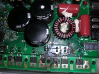
Im sure I am not the only one who sees a ton of gobldy gook inside the leftern torriod. What the heck is all that grey moosh? If the transformer is shorted you'll have to make sure it is able to be repaired or replaced before buying any other parts.
Some of the bd's were notorious for "whining" it was the torroid I think they actually vibrated. Didnt really hurt anything but was annoying and if you put your hand on it and applied pressure it would stop.
Rockford started coating them to eliminate the problem. That one looks like it was done by someone other than Rockford. I usually dont coat them like that as it would hold alot of heat.
I have used silicone and epoxy both to eliminate the whine.
Rockford started coating them to eliminate the problem. That one looks like it was done by someone other than Rockford. I usually dont coat them like that as it would hold alot of heat.
I have used silicone and epoxy both to eliminate the whine.
Some of the BD amps mainly the 1500's the torroids rubbed on the bottom cover and shorted out. This was another reason for the coating.
I will coat them and sometimes use spacers in between the sink and bottom cover.
I will coat them and sometimes use spacers in between the sink and bottom cover.
I agree, it's likely to quiet the transformer. It was a complaint from a lot of people who had the amps inside the car or could hear it when their rear seats were down.
I also avoid coating them when possible. Sometimes you just need to move the windings a bit to quiet them.
I also avoid coating them when possible. Sometimes you just need to move the windings a bit to quiet them.
Yes well said Perry dont coat them unless you have to. I only do it when I cant get the whine out by twisting or moving torroid wires.
If they are rubbing on the bottom cover it is a must if the torroid cannot be de-soldered and lowered on the board.
If they are rubbing on the bottom cover it is a must if the torroid cannot be de-soldered and lowered on the board.
Yes, certainly, I think that kind of caulk on top of the toroid, is to reduce noise and vibration from it. (putty is hard, it seems cement)
Thanks to everyone for their comments and ideas.
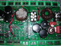
Perry, the capacitors are swollen surrounding both Q15 and Q16 regulators, perhaps in the photo is not well appreciated, but I can assure you are swollen, below.
I'm thinking about buying an oscilloscope.
This afternoon I start to get parts.
Thanks to everyone for their comments and ideas.
Perry, the capacitors are swollen surrounding both Q15 and Q16 regulators, perhaps in the photo is not well appreciated, but I can assure you are swollen, below.
I'm thinking about buying an oscilloscope.
This afternoon I start to get parts.
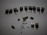
Well, I got all the pieces, apparently, I found defective.
Seankane was right, the MIC4420 was dead. (the only piece I have to ask the shop, the other pieces I have them all)
I connected an amplifier time to check the supply voltage, when I still had to desolder, Q15 and Q16 regulators.
Then, led power protection, power supply, HV, 110v and 120v up to more, but Q15 in four seconds, it gets red hot (you can not touch)
Q15 and Q16 I have removed and checked their values, contrasting them with new ones, and have a different reading (they seem to have leaks)
Tomorrow I begin to weld the new pieces.
Attachments
To replace the gate resistors R187, R186 ..... are 25 ohms and a tolerance of 1%
I wanted to know what would happen if replaced with a 5% tolerance?
I wanted to know what would happen if replaced with a 5% tolerance?
5% will be OK. If you're concerned, check the resistance of a dozen or so and use the ones that are the closest to the marked value.
I have a 1500-1bd and the pink capacitors that I believe are similar to the big ones in the pictures on the right side of the board are totally gone. What type of capacitors are these?
Well, finally today I got the part I needed, (MIC 4420)
Parts Replacement:
R72, R74, R186, R187, R188. (At the end, I found the same as the originals)
C26, C31, C57 to C63, C74. (electrolytic and tantalum)
U6. (MIC4420CT)
Q15, Q16, Q103, Q104, Q105, Q106, Q8, Q110, Q111, Q112, Q25.
Well, when connected, what happens is this:
The LED lights up protection for two seconds and then turns off.
Nothing warms up, but (now comes the good part ...) in the audio output of the speaker, I have 125V ¿.? How can it be? Is there a short circuit somewhere? I do not know if I suspect polyester capacitors ....
Attachments
Post the DC voltage on all pins of U17.
U17
Pin 1:
Pin 2:
Pin 3:
Pin 4:
Pin 5:
Pin 6:
Pin 7:
Pin 8:
U17
Pin 1:
Pin 2:
Pin 3:
Pin 4:
Pin 5:
Pin 6:
Pin 7:
Pin 8:
Almost every bd series amp I have repaired with DC voltage on the output terminals has been U17 the LM6171 BIN. Not all but most. If you have DC voltage of more than a fraction on pins 2 and 6 it is defective for sure. The only pins you should have any significant DC on are pins 4 and 7.
- Status
- Not open for further replies.
- Home
- General Interest
- Car Audio
- Rockford Fosgate 1501bd preview Repairing