
Ok I dont know if it matters it says TL494C.
Pin1=0.648
Pin2=5.138
Pin3=0.596
Pin4=2.016
Pin5=1.963
Pin6=3.762
Pin7=0.512
Pin8=8.07
Pin9=0.505
Pin10=5.380
Pin11=5.378
Pin12=5.376
Pin13=8.06
Pin14=8.06
Pin15=0.958
Pin16=0.954
Pin1=0.648
Pin2=5.138
Pin3=0.596
Pin4=2.016
Pin5=1.963
Pin6=3.762
Pin7=0.512
Pin8=8.07
Pin9=0.505
Pin10=5.380
Pin11=5.378
Pin12=5.376
Pin13=8.06
Pin14=8.06
Pin15=0.958
Pin16=0.954
Are you sure that you have the pin numbering right?
Did you have the black probe on the main ground?
Did you have the black probe on the main ground?
Ok so looking at your diagram. I flipped the top row. Sorry about that.
Pin1=0.648
Pin2=5.138
Pin3=0.596
Pin4=2.016
Pin5=1.963
Pin6=3.762
Pin7=0.512
Pin8=8.07
Pin9=0.954
Pin10=0.958
Pin11=8.06
Pin12=8.06
Pin13=5.376
Pin14=5.378
Pin15=5.380
Pin16=0.505
Pin1=0.648
Pin2=5.138
Pin3=0.596
Pin4=2.016
Pin5=1.963
Pin6=3.762
Pin7=0.512
Pin8=8.07
Pin9=0.954
Pin10=0.958
Pin11=8.06
Pin12=8.06
Pin13=5.376
Pin14=5.378
Pin15=5.380
Pin16=0.505
I think I found the voltage problem. When I connect the remote turn on lead the voltage gets dropped down to 8.06vdc coming into the amp. Once I remove the remote turn on it goes back to 12.5
The low voltage could be forcing it into low voltage shutdown.
How much current is it drawing from the 12v supply when the remote is applied?
How much current is it drawing from the 12v supply when the remote is applied?
If there are no shorted output transistors (check every one), set the bias fully counter-clockwise for both channels. Does the current draw drop?
Does the amp power up normally?
Does the amp power up normally?
The most important thing to remember is that, when they're free, the will lift with VERY little force. Do not force them up.
They are soldered down. You will have to heat the insulator from the back after removing the board from the sink and cleaning all heatsink compound from the insulator.
Do you have a small butane torch (not a large propane torch) or a heat gun?
Do you have any binder clips (like those used to bind large stacks of papers?
The amp will have parallel outputs which can make it appear that more are shorted than there are. Find the ones with the lowest resistance from leg 1-2 and cut all legs free. Does this allow the amp to power up?
The following is the basic procedure for removing the transistors but it can wait until we determine how much damage there is to the rest of the amp.
Use the binder clips on the adjacent transistors to prevent them from lifting. Heat the back of the insulator (being careful not to heat the board) until the defective transistor will slide off of the insulator.
So on one side i have
103ohms
103ohms
83.4ohms
2.2ohms
22.1ohms
22.2ohms
try cutting the 2.2 out?
The other side:
7.75M ohms
7.75M ohms
7.75M ohms
14.6ohms
14.0ohms
5.4ohms
cut the 5.4?
103ohms
103ohms
83.4ohms
2.2ohms
22.1ohms
22.2ohms
try cutting the 2.2 out?
The other side:
7.75M ohms
7.75M ohms
7.75M ohms
14.6ohms
14.0ohms
5.4ohms
cut the 5.4?
So I cut the 2 and the power led turns on and I have
30.34M ohms
30.35M ohms
30.07M ohms
24.5ohms
23.2ohms
cut out
other side
7.04M ohms
7.04M ohms
cut
3.9ohms
23.7ohms
23.8hms
Do you think the 3.9?
30.34M ohms
30.35M ohms
30.07M ohms
24.5ohms
23.2ohms
cut out
other side
7.04M ohms
7.04M ohms
cut
3.9ohms
23.7ohms
23.8hms
Do you think the 3.9?
- Home
- General Interest
- Car Audio
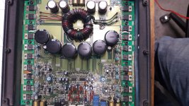
- Rockford 500a2