In differential mode, post the drive waveform for one high-side and one low-side output FET. Ch2 on the source leg. Scope on DC coupling, 5v/div and the timebase set to show 3-4 full cycles.
I'll get on this as soon as I can. I'm also doing a software contract job,
I hid my good scope robes somewhere in my mancave.
Al
I hid my good scope robes somewhere in my mancave.
Al
You can get probes that are perfectly suitable for $5 each on ebay if they're going to be hard to find.
Sorry it's taken so long, been very busy.
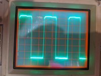
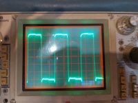
Was getting ready to do the differential test for ya, but before I got through hooking up both scope probes I think I see the problem. Question, shouldn't the signal on the source pins on both sides be the same amplitude, just out of phase by 180. The reason I stopped short of doing the whole differetntial test is on one side the source signal is a slightly distorted square wave and 12 volts peak to peak. on the other side I got 120 volt pretty nice square wave.
For the differential test 120 volt pp. All sweeps are 2 us per division.
Now I put the words good and bad in the file descriptions for reference only. Not making an assertion.
Al
Attachments

The differential signal isolates the drive signal from the rail-rail oscillation. The entire signal will be 10-12v and will be displayed from the reference line (vertical center of display) up about 12v.
By "signal" do you mean the real audio signal? Because in this test I'm not driving the amp at all.
I'm referring to the signal that's being used to drive the output FETs so that they can do their job.
With no input (no reason to produce an audio signal), the amp is simply swinging rail-rail.
With no input (no reason to produce an audio signal), the amp is simply swinging rail-rail.
I think I get that, but since this is my first class 'D' amp to work on I do not have a good point of reference.
Anyway, back to my previous post, remember me pointing out that the source on one side was 12 volt pp, and the other was 120 volts pp, isn't that an indicator of a problem? I'm guessing both should be either 12 or 120 volt. I think you commented earlier that the sources should be 12 volts pp. The fact that the source was 120 volt pp on one side suggests I got a shorted mosfet maybe. Do you agree?
Anyway, back to my previous post, remember me pointing out that the source on one side was 12 volt pp, and the other was 120 volts pp, isn't that an indicator of a problem? I'm guessing both should be either 12 or 120 volt. I think you commented earlier that the sources should be 12 volts pp. The fact that the source was 120 volt pp on one side suggests I got a shorted mosfet maybe. Do you agree?
The job of the output FETs is to switch between the power supply rails. The drive for the FETs is driven to the gate but is referenced to the source.
The high-side source is swinging between the rails. This means that the gate drive has to float with the source. If you look at the gate with the ground as a reference (not differential), you see the gate drive added to the floating source waveform and that makes it difficult to know if the gate drive is what it should be.
The differential mode readings are also better for the low side because you can get better resolution.
Using DC coupling with differential measurements lets you confirm that the gate drive is fully going back to the source (to turn the FET fully off).
Sounds like you’re losing the input signal somewhere, the pair of amps I worked on didn’t have any issues in that area so I’m afraid I won’t be much help to you there. What I usually do in that situation is try to follow the input signal through the pre card as it passes from opamp to opamp, see if you can locate one where the signal goes in but doesn’t come out. And use a much lower frequency, rockfords have really good crossovers so I wouldn’t be the least bit surprised if a 1khz input got completely rolled off to nothing. I use 80hz for testing.
Pretty sure I found the problem. The +15 volt rail is missing on the daughter board of the audio input circuit. They do such a darn good job of applying that circuit board paint its very difficult to figure out where its gone missing.
Al
Al
Well I did also. Both rails were good on the main board and the main audio input board, just the small daughter board that's plugged and soldered to the audio input board.
al
al
Yea I got the schematic. Want a copy?
Anyway, I spent a couple of hours trying to trace through tiny via's and lands to figure out where the break is. I got a brain storm as I was going to sleep last night. I'll drag the amp back out in a bit and give it another go.
P.S. I asked RF for a printed circuit diagram. We'll see if they follow through again.
Al
Post it here if Rockford didn't designate it as confidential when they sent it to you (released diagrams still have confidential printed on the diagram).
Unless you have no way to get a computer near your bench, the digital PDF document is generally better. If they won't send a paper copy, many places will print it for you.
Unless you have no way to get a computer near your bench, the digital PDF document is generally better. If they won't send a paper copy, many places will print it for you.
There aren't many header pins. Use your meter to find the connection between the regulator output and the header by touching every pin with your meter.
If you find none, go from the PS pin of the ICs to the header pins.
It's not likely to be broken from both points. If you find the connection to either the regulator or the IC to the header, that will narrow down the area to search.
If you find none, go from the PS pin of the ICs to the header pins.
It's not likely to be broken from both points. If you find the connection to either the regulator or the IC to the header, that will narrow down the area to search.
- Home
- General Interest
- Car Audio
- Robert Fosgate Power Rails