Export the data from the DATS measurement and Hornresp to .zma files, then import them into REW. It will be much easier to compare them that way. Those to graphs have different axes, which makes them difficult to compare. Something different does seem to be happening though.
OK - Here goes!Oh, I forgot, please share your Hornresp sim parameters, thanks!
Firstly, impedance
Now the Hornresp screens
Now for the sake of an easy comparison, I shoehorned a JBL 2217 into the box. it simulated very well indeed, despite being a fourteen inch driver. With the mic just in the horn mouth, here's the comparison between the two drivers, illustrating that it's definitely a box problem and not a driver one. There's still at difference of at least 12db from 100 to 50hz, although the difference did improve with the other driver.
I did make one small deviation from the design and that was to use two braces on the long panels (original design calls for one) as I was using fairly cheap plywood. The only picture I have from construction is this one, but you should get the idea. I suppose this may have created 3 separate paths as they also run almost the full length of the panels.
Could the double lot of braces be stopping some of the magic from happening in the long horn path? I could maybe cut the top off the box and "swiss cheese" them with a long forstner bit on a drill.
I am confident that all accessible panels are not leaking, which only leave the highlighted panel below (not my build) as a potential place for a leak.
Cutting the top off would allow me to ensure that at least one side doesn't have leaks, however looking at the previous picture that shows the bottom of my build with glue expanding out (and remembering how much glue I used when putting the top on to make sure I didn't have leaks), I don't think that this is very likely.
Any help is greatly appreciated. This box is so stupidly loud at 100hz. It would be great the get that same performance down lower before the box becomes firewood.
Hello laxandredeyed,
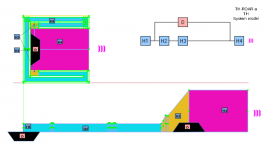
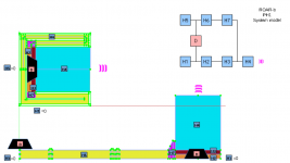
Just a note, while people are helping you in the analysis for the issue at the lower part of the frequency spectrum, I'd like to mention that modeling ROAR as Tapped Horn (TH) in hornresp looks less accurate then modeling as paraflex type 1 (PH1), probably when it was developed the paraflex model might not be available, but once they are now, for my personal simulations I use it.
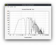
Check the data attached, as you can see, it's closer to your real measurements compared to the TH model, regarding all the dip after 150hz. There are some difference in the scale from Hornresp and from your measurements, but you can check overlaps the curves to compare if it worth for you.
Just a note, while people are helping you in the analysis for the issue at the lower part of the frequency spectrum, I'd like to mention that modeling ROAR as Tapped Horn (TH) in hornresp looks less accurate then modeling as paraflex type 1 (PH1), probably when it was developed the paraflex model might not be available, but once they are now, for my personal simulations I use it.
Check the data attached, as you can see, it's closer to your real measurements compared to the TH model, regarding all the dip after 150hz. There are some difference in the scale from Hornresp and from your measurements, but you can check overlaps the curves to compare if it worth for you.
Attachments
Hi there Lordsansui,Hello laxandredeyed,
Just a note, while people are helping you in the analysis for the issue at the lower part of the frequency spectrum, I'd like to mention that modeling ROAR as Tapped Horn (TH) in hornresp looks less accurate then modeling as paraflex type 1 (PH1), probably when it was developed the paraflex model might not be available, but once they are now, for my personal simulations I use it.
Check the data attached, as you can see, it's closer to your real measurements compared to the TH model, regarding all the dip after 150hz. There are some difference in the scale from Hornresp and from your measurements, but you can check overlaps the curves to compare if it worth for you.
Are the figures you have shown in the model above correct for a ROAR 12 and my woofer? I don’t quite understand the parallel function on Hornresp yet!
yes, they are. it might be some small differences because I made it rushing. Attached you can find a system model reference for each one so you can adjust the simulations using TH or PH1 according to the plan you have.
Attachments
Thank you Lordsansui! Your help is appreciated.
I’m still down 10db on the paraflex model at 50ish hz.
What is unknown to me for certain is whether I am lacking efficiency down low, or whether the ROAR subwoofer has delivered higher than predicted efficiency up high. I guess I need some other boxes to compare with.
I’m still down 10db on the paraflex model at 50ish hz.
What is unknown to me for certain is whether I am lacking efficiency down low, or whether the ROAR subwoofer has delivered higher than predicted efficiency up high. I guess I need some other boxes to compare with.
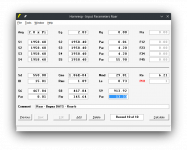
Measured with DATS v3. The speaker I have is labelled Beyma 112nd/w, but does not have the heat sink on the magnet like the do on Beyma’s spec sheets. Measuring with DATS I god wildly different specs, including as 60hz resonant frequency. I ran the test multiple times and got the same answer. The simulations are with the DATS measurements.mms 29 grams ?
29 grams surely does seem tonne on the low side, though
29 grams surely does seem tonne on the low side, though
Beyma 112nd/w electro-mechanical values derived from Thiele-Small values given at https://usspeaker.com/beyma 112ndw-1.htm
Sd = 550.00
Bl = 18.37
Cms = 1.28E-04
Rms = 2.12
Mmd = 78.47
Le = 1.10
Re = 5.60
I ran the two speakers through DATS again. I'd stuffed up the added mass when calculating Vas (and hence Mmd). I am completely convinced that the 112nd/w I have are a different iteration of the model used with Beyma's published specs. They look different, but are still labelled 112nd/w. Perhaps they have been reconed.Beyma 112nd/w electro-mechanical values derived from Thiele-Small values given at https://usspeaker.com/beyma 112ndw-1.htm
Sd = 550.00
Bl = 18.37
Cms = 1.28E-04
Rms = 2.12
Mmd = 78.47
Le = 1.10
Re = 5.60
After triple checking everything with DATS, the following parameters are correct for my two drivers (both measured similarly)
They still model very similarly in Hornresp with the ROAR 12 design, however and I'm still no closer to working out why I'm 15db down at 50hz vs the simulation.
In order to try and find some more info, I measured the ROAR12 next to a Bill Fitzmaurice Omni 15 loaded with a 3015LF. Same amp voltage, same mic distance, same positioning. Does this suggest that perhaps the box I have built is delivering the low end from the simulations, but is overperforming at the high end? The 3015LF has a sensitivity of around 99db 1w/1m
The Omni shows a dip at a similar frequency and the comparison verifies the serious sensitivity of the ROAR in the upper bass range. While the dip in a similar location on the Omni may suggest environmental factors are at play, I have replicated the same 15db drop in the middle of a paddock, with the mic in the horn mouth and 2m from the box loaded against a wall, and with 2 different kinds of drivers!
It delivers an amazingly cutting low end with a bass guitar (part of its intended use, where high fidelity is not required), but just does not cut the mustard for recorded music.
Surely someone has an idea what could be going on here?
I would not measure the Roar in the horn mouth. Chose a more realistic measuring position. More like a meter away from the horn mouth. Try the same with the other box, for comparison.
For the TSP measuring error: When the sampling frequency of the software does not match the one of the soundcard, you may get strange results, like too high Fs etc.
For the TSP measuring error: When the sampling frequency of the software does not match the one of the soundcard, you may get strange results, like too high Fs etc.
Thanks - I have measured the ROAR a number of ways - same damn result every time! I actually was starting to wonder if my soundcard was non linear.I would not measure the Roar in the horn mouth. Chose a more realistic measuring position. More like a meter away from the horn mouth. Try the same with the other box, for comparison.
For the TSP measuring error: When the sampling frequency of the software does not match the one of the soundcard, you may get strange results, like too high Fs etc.
I've measured a few other woofers with DATS and have gotten results close to published specs. These Beymas a just a funny beast. I will check sampling frequencies all the same.
Thanks - I have measured the ROAR a number of ways - same damn result every time! I actually was starting to wonder if my soundcard was non linear.
I've measured a few other woofers with DATS and have gotten results close to published specs. These Beymas a just a funny beast. I will check sampling frequencies all the same.
I just checked my sound card settings and the DATS hardware is configured for 2 channel 44.1khz as per the manual. Thanks for the tip, all the same.For the TSP measuring error: When the sampling frequency of the software does not match the one of the soundcard, you may get strange results, like too high Fs etc.
This strange dip did not appear in my ROAR12 build. My ROAR12 did loose a few dB in the lower end of the passband compared to the midbass peak, but it was a smooth gently sloping curve. The ROAR does need high power drivers with lots of Bl and a quite sturdy cone that can take the pressure of two series coupled QW resonators. It seems like the driver couples well to the front resonator, but there is some problem with its coupling to the tapped pipe section. It does not seem to be able to drive the TP.
This is why I believe it was a leak somewhere. A leak in the tapped pipe section could give this strange dip in the response.
I finally found my old measurement of my ROAR12 loaded with a B&C 12PS100. We designed the ROAR12 for the B&C 12TBX100 which has more Mms and more Bl. But there is a quite large drop in output from 60 Hz and down. More then I remembered. It did not have that strange dip in the response. This is measured with the microphone 50 cm from the mouth indoors in the middle of a large room.

A comparison between a Hornresp-sim and the actual measurement of my ROAR12 (B&C 12PS100). The discrepancy around 52 Hz is due to the large surface area inside the split path Tapped Pipe section. It does lower the Q of the response of the TP section quite profoundly. This is why we designed the ROAR-series with a slight "roller coaster" simulated response - too large cross section area of the TP section to pre-correct for this simulation-artifact.
environmental factors are at play
Yes, it looks like,
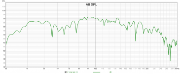
Probably your environment has some walls too close to the box, to confirm it, you could run Real Time Analyse (RTA) and keep the microphone at fixed position and now moves your box, if you change the relative position to the wall it will change the dip position and or magnitude. See attachment one measurement i made in a semi-open environment, looks like I got at least 3 different frequencies subtracting with my box (~56Hz, ~66Hz and ~78Hz), it kills my bass.
Regarding the mmd, just to confirm, the environment also may effect the T?S parameters too, so, are you measuring the driver outside the box and suspended in the air?
Attachments
It could also be due to box losses, which are not included in the Hornresp model. However, your sim comparison shows your measured results being higher than the Hornresp sim for most of the measurement, which IMO is not going to be possible. I think the relative level of the measured result in comparison to the Hornresp sim needs to be adjusted.The discrepancy around 52 Hz is due to the large surface area inside the split path Tapped Pipe section.
- Home
- Loudspeakers
- Subwoofers
- ROAR 12 -Disappointing Results