Lets be clear on this :
There are power amplifier losses that require a voltage
difference between the rails and output voltage.
At low output current this is basically a minimum drop-out voltage.
At high currrent it can increase due to resitive losses for Bipolar
output stages and in the case of Mosfets increase much faster
due to output current higher gate drive voltage requirements.
It is not reasonable to only assume power supply droop,
and the ripple voltage below this for minimum voltage.
🙂 sreten.
@tab:
greetings to ravensburg. i was born in konstanz!
@sreten
yes, my estimation with 3V drop in the output stage is very optimistic
if we consider the high output current. depending on the VAS stage
and the BJT output stage this can easily exceed 5V.
in MOSFET designs it can easily exceed 10V......
cheers
markus
know someone concretely at the AV400 (Holtons Symm Amp) , if it is possible then to add a small help PowSup witch set the Voltage for the driver stage in the + and - direction about 10 V higher ?
... little modification ... much more power out ?!
AND much more cheaper than lager cap's
why not often used ?
... little modification ... much more power out ?!
AND much more cheaper than lager cap's
why not often used ?
hi tab!
in mosfet designs this is often done. there you can get a benefit of
about 10V or little more.
In BJT designs the benefit will ususally not be more than 3-5V and
due to this it is not worth the additional efforts.
Please note that our ears have a logarithmic sound pressure
sensitivity. A difference of about 2db will be required to notice that
it has become louder.
2db means about 58% more power!!!!!
So in order to get noticeable more sound pressure you will have to
increase the power much much overproportional....
That's why you can listen to music at normal levels with a 2W amp, but
for disco you need several kW.
@ Choco
Yes your right ... but ... you know, it's most for the HEART than for the Ears.
I decided to build this amp ( it is half finished) and I simply feel better by getting the last possible out of it.
🙂
Yes your right ... but ... you know, it's most for the HEART than for the Ears.
I decided to build this amp ( it is half finished) and I simply feel better by getting the last possible out of it.
🙂
Yes. You can calculate peak power based on available voltage and the amplifier working voltage, but I don't know any math that'll get you to how much distortion there will be at that level given any particular topology.sreten said:
Sorry but you've lost me on this one.
Transistor amplifiers distort usually by running out of rail voltage,
or more to the point rail voltage - working voltage of the amplifier.
🙂 sreten.
Example - most car CD players spec their power at around 50 watts peak per channel. With MOSFET outputs they assume minimal transistor losses. With 14.1 VDC power and a bridged amp, you get 14.1V peak which is 50 watts peak into 4 ohms.
That should be 10 vrms and 25 wrms, but a typical spec says 20 wrms @ 2% THD. If you back off to .05% THD (or whatever the amp is capable of) you get even less. So the numbers you'll get from power supply calculations don't necessarily mean much, if you care about "undistorted" power.
🙂))
yes for the heart.
but your heart should also beat for reliability, so i would
not propose to squeeze the last watt....
It simply makes no difference if amp has 400W or 500W.
But it makes a difference if it fails during a party or not.
If you increase the supply of the input stage and VAS stage
of your amp please make sure that you will not overload
some components....
May be a stabilized separate +/-70V supply for the input stages and VAS stage will help, while the output stage runs from the unstabilized
supply.
If you have a MOSFET output you might add some voltage
clamping for the Ugs of the FETs (i.e. antiseriell Z-diodes from
gate to source of the FETs), if there isn't already a similar limiting
circuit implemented.
In a BJT design you might limit the output of the VAS against the
unregulated rails with some fast diodes.
Good luck
Markus
@ Choco
Yes... Yes ... I can't avoid to agree you. 🙂
But on the other hand you can go further and say, why not 200W then why not 50W why not...
I think it simply sounds better if the amp have headroom for strong controlling the Speaker's moving mass.
If I realize this modification I'll report the results in this forum.
Ps. V-limiting Diodes are already integrated.
@maylar:
I agree to your distorsion considerations.
But during a party nobody notices 1% or 2% distorsion.
Only hard clipping will be noticed.
If it is not run at a party a 400W amp will have a lot of headroom
and will show much lower distorsions (if idle current is set properly).
Sleep well everybody
Markus
Take a look at the following: http://www.signaltransfer.freeuk.com/
click on App Notes 1 & 2
This is the clearest cookbook estimate proceedure for comming up with RMS power I've seen yet.
Of course, neither this of any of the methods decribed in other posts can be comparred to what you may read in commercial specs which are often written by the marketing department!!
"rms" power
Hi guys:
I should recognize that your oppinions are righ, but I must recall that the "rms" value was defined just for current or voltage, but not for power.
A "rms" voltage value will produce the same power dissipation in a pure resistor when is replaced with a d. c. voltage having the same value (1 V).
I mean if a pure resistor is (under the same conditions) dissipating 1 watt with a "rms" voltage of 1 V, then will also dissipate 1 watt when the a. c. signal is replaced with 1 V d. c.
An exact and valid phrase can be constructed for current, just replacing the word "voltage" with "current" when talking of the magnitud or "ampere" when doing that with the unit.
Then, what is the meaning for "rms" power?
I understand that spec as "honest" power, because Chinese introduced horrible specifications for power, followed by Sony that introduced "PMPO" watts.
But there is not any technical reason for talk about "rms" power.
Regards
Hi Hugo!
...true words...
Yes the rms values for voltage and current are a simplyfied
math tool to enable power dissipation calculations in linear resistive loads. This power dissipation is the average power dissipation of the resitor. For a DC signal this is clear. Constant voltage times constant current gives a constant power. So there is no difference
between max, mean and rms values.
For alternating signals things are getting more complicated.
The name rms (derived from: root mean square) are somehow
misplaced when we talk about the result in watts.....
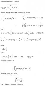
Mathematical you get the rms voltages and currents from
the root of the average of the squared signal.....
For sinusodial signals this also delivers the well known factors 1.41 or 0.707 .
This makes life easier than always handling with u(t) and i(t),
which is already with sinusodial signals and without phase shift (inductive or capacitive load??!!!) somehow driving us crazy.
i(t)= Imax *sin (wt)
u(t) = Umax * sin(wt)
p(t) = i(t) * u(t) = Imax * Umax * (sin(wt))^2
Please note while voltage and current show positive and negative
values, the power will never get negative. No power is feed back from the resistive load to the amp. Of course in reality you have a complex load with phase shift and some energy will swing back....
Back to our rms-power, which is of course a really unfortunate name
because in fact it is more an average power than an rms-value!!
We can caculate
P = Urms*Irms, but have to keep in mind that this
is exactly the same as
P = average(p(t)) = average( Imax * Umax * (sin(wt))^2)
Well, nevertheless the wording "rms-power" has somehow established for honest power......
You can also play a little bit with a simulation software.
Simply simulate a resitor connected to a sinusodial voltage.
Then display the current and the rms value of the current.
The same with the voltage.
Next plot: current times voltage ==> shape of a squared sinusodial (no negative part anymore, but double frequency ....)
Average of this plot is the same as the power calculated from
Irms*Urms.
Please note that you have read the avg and rms values only at that points , when a full period or multiple full periods are finished.
Have fun
Markus
...true words...
Yes the rms values for voltage and current are a simplyfied
math tool to enable power dissipation calculations in linear resistive loads. This power dissipation is the average power dissipation of the resitor. For a DC signal this is clear. Constant voltage times constant current gives a constant power. So there is no difference
between max, mean and rms values.
For alternating signals things are getting more complicated.
The name rms (derived from: root mean square) are somehow
misplaced when we talk about the result in watts.....
Mathematical you get the rms voltages and currents from
the root of the average of the squared signal.....
For sinusodial signals this also delivers the well known factors 1.41 or 0.707 .
This makes life easier than always handling with u(t) and i(t),
which is already with sinusodial signals and without phase shift (inductive or capacitive load??!!!) somehow driving us crazy.
i(t)= Imax *sin (wt)
u(t) = Umax * sin(wt)
p(t) = i(t) * u(t) = Imax * Umax * (sin(wt))^2
Please note while voltage and current show positive and negative
values, the power will never get negative. No power is feed back from the resistive load to the amp. Of course in reality you have a complex load with phase shift and some energy will swing back....
Back to our rms-power, which is of course a really unfortunate name
because in fact it is more an average power than an rms-value!!
We can caculate
P = Urms*Irms, but have to keep in mind that this
is exactly the same as
P = average(p(t)) = average( Imax * Umax * (sin(wt))^2)
Well, nevertheless the wording "rms-power" has somehow established for honest power......
You can also play a little bit with a simulation software.
Simply simulate a resitor connected to a sinusodial voltage.
Then display the current and the rms value of the current.
The same with the voltage.
Next plot: current times voltage ==> shape of a squared sinusodial (no negative part anymore, but double frequency ....)
Average of this plot is the same as the power calculated from
Irms*Urms.
Please note that you have read the avg and rms values only at that points , when a full period or multiple full periods are finished.
Have fun
Markus
- Status
- Not open for further replies.
- Home
- Amplifiers
- Solid State
- RMS Power