Hi Daniel,
The Sanyo 1209/2911 are equivalents of the Toshiba's.
VAS transistors for sale 2SA1360Y/2SC3423Y,2SA1209S/2SC2911S and KSA1381E/KSC3503E
When looking to the schematic, Q19 and Q20 have about 100mW of dissipation.
The Toshiba 2SC2705/2SA1145 are TO-92MOD package and can dissipate 800mW, these have the same die as the 2360/3423.
Q8 (CCS) can also be replaced by a common TO126 BJT: MJE340 for example.
Last edited:
Dear All,
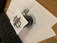
I built the amplifier based on the original plans. Now I setting up the quiescent current.
Do you think the values in the picture are correct or could I go even higher?
Listening the amp I did not recognize any distortion by maximum allowed input signal level.
After one hour run, the heatsink warmed up little therefore I can touch it easily with bare hands.
I measured 8mV between the legs of two emmiter resistor series, while over the half-supply 0.2 A ran through.
The voltages on the front end psu are +-43VDC and on the power stage +-38 VDC.
I want to load the amp with 8R speakers in the future.
Thank you for the help in advance!
Best regards,
Arcor
Picture:

https://i.postimg.cc/nrNm3dhv/IMG-20210901-154336-034742.jpg
I built the amplifier based on the original plans. Now I setting up the quiescent current.
Do you think the values in the picture are correct or could I go even higher?
Listening the amp I did not recognize any distortion by maximum allowed input signal level.
After one hour run, the heatsink warmed up little therefore I can touch it easily with bare hands.
I measured 8mV between the legs of two emmiter resistor series, while over the half-supply 0.2 A ran through.
The voltages on the front end psu are +-43VDC and on the power stage +-38 VDC.
I want to load the amp with 8R speakers in the future.
Thank you for the help in advance!
Best regards,
Arcor
Picture:
https://i.postimg.cc/nrNm3dhv/IMG-20210901-154336-034742.jpg
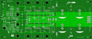

Actually I design the front end psu (active rectifier, lt3062) and rectifier board (active rectifier).
After that I will order circuit boards.
After that I will order circuit boards.


I will order a couple of boards next week.
If someone is interested, contact me.
Do you plan to build an amp and psu board to verify there are no unforeseen errors?
No, I am brave 😉
I can send all layers and the schematic to someone to verify it.
Who is ready to this job?
Daniel
I can send all layers and the schematic to someone to verify it.
Who is ready to this job?
Daniel
Hi roender,
It seems like I cannot send you a PM (now called conversation) through the forum anymore. If you're able to do so, could you please contact me, perhaps send me your email address. I have a quick question for you.
Happy New Year!
Do
It seems like I cannot send you a PM (now called conversation) through the forum anymore. If you're able to do so, could you please contact me, perhaps send me your email address. I have a quick question for you.
Happy New Year!
Do
Hi Daniel,
The message is addressed to Roender, he designed this amplifier and started the thread.
Thanks
Do
The message is addressed to Roender, he designed this amplifier and started the thread.
Thanks
Do
- Home
- Amplifiers
- Solid State
- RMI-FC100, a single stage audio power amplifier